Fuel System
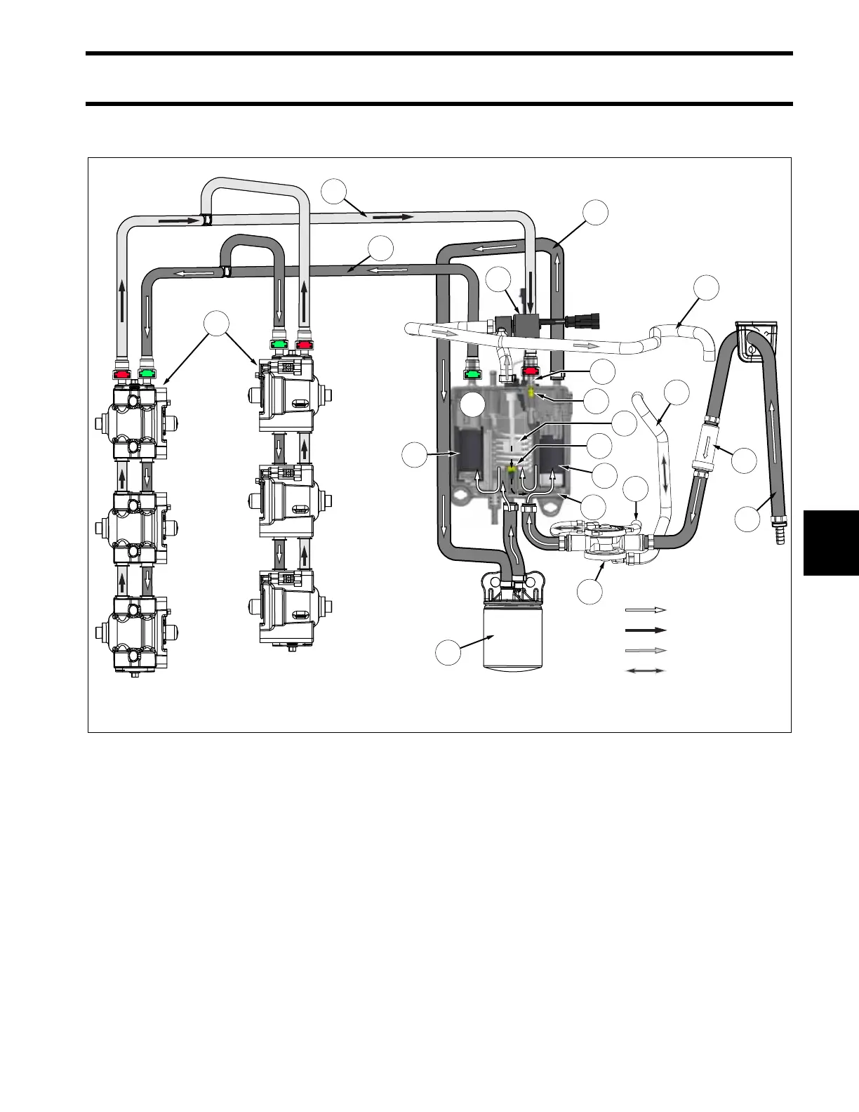
Fuel System Flow Diagram (AG & Newer)
151
7
Fuel System Flow Diagram (AG & Newer)
1.
2.
3.
4.
5.
6.
7.
8.
9.
10.
Fuel supply from boat fuel system
Inline fuel filter (250 micron)
Fuel lift pump (crankcase pulse)
Pulse hose to cylinder #1
Pulse hose to cylinder #4
Fuel pump/vapor separator assembly
Internal passage
Electric fuel lift pump
Fuel supply hose to water separating fuel filter
Water separating fuel filter (10 micron)
11.
12.
13.
14.
15.
16.
17.
18.
19.
20.
Electric fuel circulation pump
Fuel supply rail (green connector)
Fuel injector(s)
Fuel return rail (red connector)
Fuel return filter
Pressure regulator (high pressure)
Pressure regulator (low pressure)
Fuel level float
Fuel vapor vent solenoid
Fuel vapor vent hose to plenum
009585
14
2
1
9
11
10
6
12
13
8
19
20
7
17
18
15
16
3
4
5
Fuel Supply
Fuel Return
Fuel Vapor
Crankcase Pulse