115
Electrical and Ignition
Ground Circuits
6
Ground Circuits
All ground circuits are essential to reliable out-
board performance. Make sure all ground connec-
tions are clean and tight. Refer to wiring diagrams
for specific wiring details.
EMM Ground Tests
Disconnect the battery cables at the battery.
Use an ohmmeter to check continuity of ground
circuits. Calibrate the ohmmeter on the high ohms
scale. Resistance readings for all ground circuits
should be 0 Ω. Refer to wiring diagrams.
Additional Ground Tests
Check connections and continuity at the following
locations:
• Main battery ground terminal.
• Check continuity between ground terminals at
port and starboard main harness grounds.
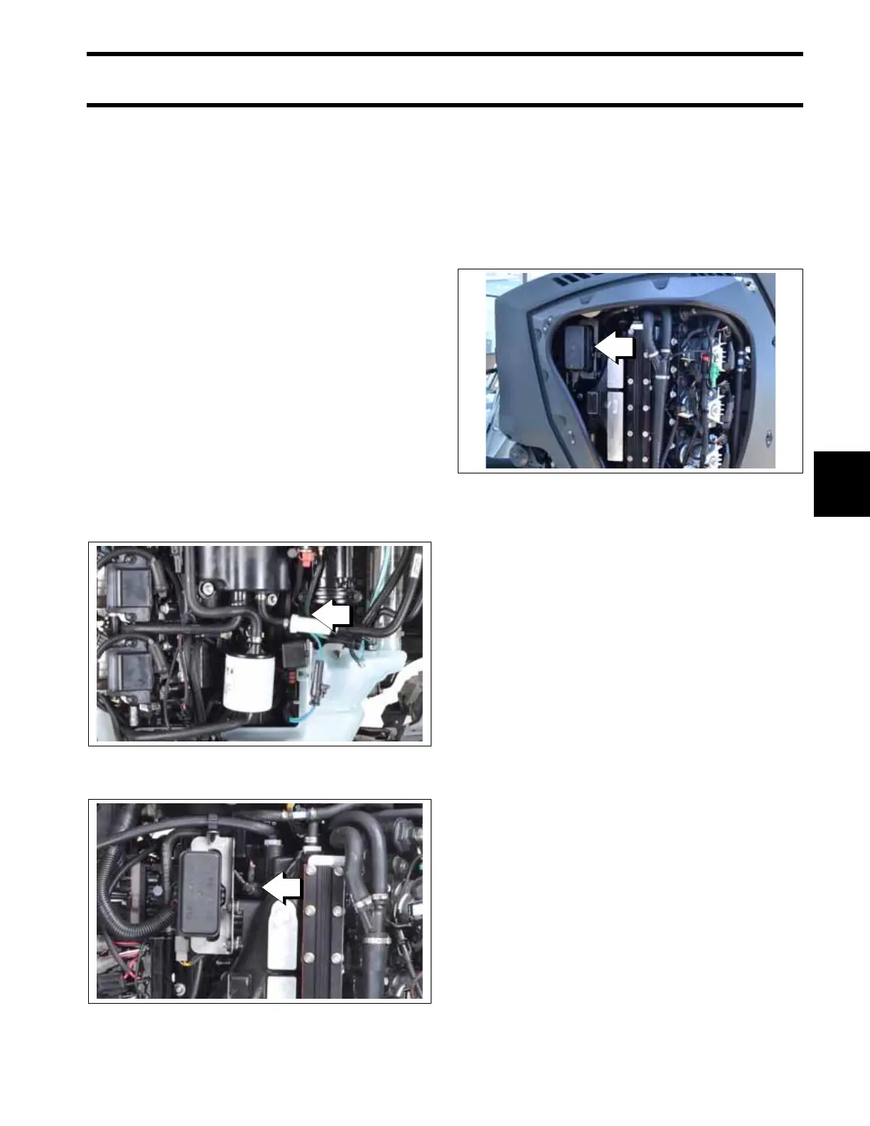
Fuses
The engine harness circuits are protected by auto-
motive style minifuses and relays.
A fuse panel is located on the port side of the
powerhead, fastened to a bracket near the front of
the powerhead.
IMPORTANT: Repeat failures of fuses could be
the result of faulty connections or accessories. The
12 V accessory circuit (purple wire from terminal
“A” of key switch) is often used to power accesso-
ries.
1. Main engine harness ground (Starboard)
Located behind inline fuel filter
009174
1. Main engine harness ground (Port)
009175
1. Fuse panel
009147