133
Electrical and Ignition
Flywheel and Stator Servicing
6
Test Procedure
Make sure red and black wires are connected to
12 V battery power supply.
Set voltmeter to 12 VDC scale. Connect test leads
to terminals “A” and “B” of TNT motor connector.
Use a wire jumper to alternately connect B+ to ter-
minals “1” and “2” of tilt and trim switch connector.
The meter must indicate battery voltage (12 V)
with B+ connected to either terminal.
Flywheel and Stator Ser-
vicing
IMPORTANT: Weak flywheel magnets can
cause low alternator output and affect outboard
performance.
An accurate test of alternator output can help
determine the flywheel’s condition. Refer to
Charging System Tests on p. 126.
Flywheel Removal
Removal and installation requires removal of the
engine covers and frames.
• See Cover Removal on p. 60.
• See Frame Removal on p. 64.
• See Center Frame Removal on p. 67.
Use a #2 Posi-Drive screwdriver to remove the six
screws from the air duct cover. Then remove the
air duct cover.
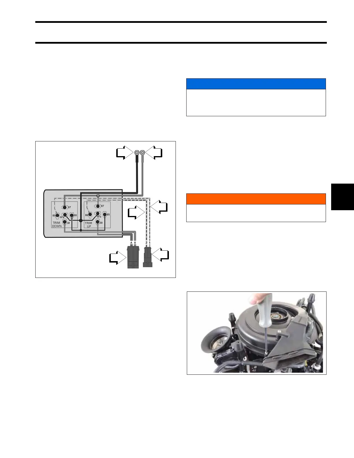
Tilt and Trim Module Diagram
1. Green/white wire
2. Blue/white wire
3. B+, red wire
4. B–, black wire
5. TNT motor connector
6. TNT switch connector
002063
NOTICE
Perform the timing verification procedure
after flywheel replacement.
Refer to Timing Adjustments on p. 136.
WARNING
To prevent accidental starting while servic-
ing, disconnect battery cables at the battery.
009333