Stern and Swivel
DPS System Tests
304
DPS System Tests
The DPS module circuits can be tested on or off
the outboard.
Disconnect the battery cables at the battery. Dis-
connect the electrical connectors from the DPS
module.
Steering Ground Circuits
Use a digital multimeter with appropriate test
probe leads to measure sensor circuit resistance.
Connect the positive meter lead to the DPS Mod-
ule connector/ wire listed in the table.
Connect the negative meter lead to engine
ground.
Results:
• Readings as listed in table indicate circuit is
good.
• No reading (OL or ∞) indicates an open circuit.
• A reading of zero (0) indicates an short circuit.
Replace faulty module.
Steering Supply Circuits
Use the diode test function of a digital multimeter
to check the supply circuits.
Connect the BLACK meter lead to the wire listed
in the table, connect the RED meter lead to
engine ground.
Results:
• Readings as listed in table indicate circuit is
good.
• No reading (OL or ∞) indicates an open circuit.
• A reading of zero (0) indicates an short circuit.
Replace faulty module.
NOTICE
Use appropriate test leads or adapters such
as Test Probe Kit, P/N 342677, when perform-
ing electrical tests.
NEVER pierce the insulation of the engine
wiring, or use any piercing-style test probe.
Piercing insulation damages the wire and can
cause other unintended electrical problems.
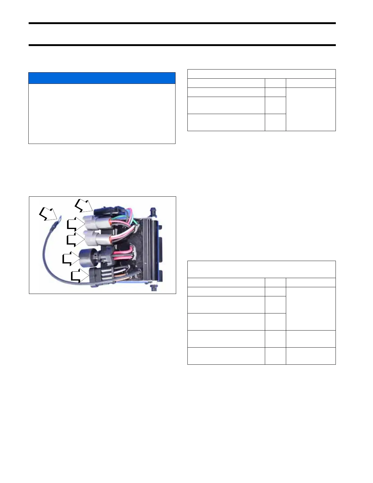
DPS Module Connectors
009402
1. Steering Position
2. Pressure Sensor 2
3. Pressure Sensor 1
4. Steering Motor
5. CANbus (communication)
6. Ground (to port engine ground screw)
DPS Module Ground Circuit
Connector/ Wire Pin Result
Steering Position/ Black 3
<1Ω
Pressure Sensor 2
/ Black
C
Pressure Sensor 1
/ Black
C
DPS Module Steering Supply Circuit
(Diode Test)
Connector/Wire Pin Result
Steering Position/ Red 1
approximately
0.5 VDC
Pressure Sensor 2
/ Red
A
Pressure Sensor 1
/ Red
A
Steering Motor/ Red 2
1.2 to 1.4
VDC
Steering Motor/ Red 1
1.4 to 1.55
VDC