Electrical and Ignition
Sensor and Circuit Tests
118
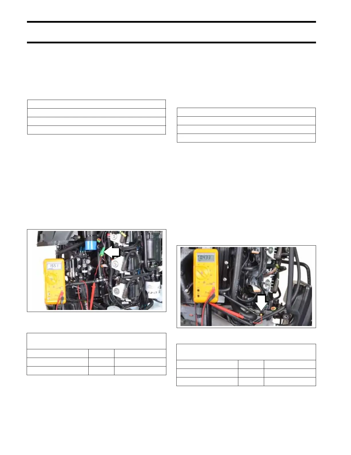
Engine Temperature Sensor Test
Remove the electrical connector from the engine
temperature sensor.
Use a digital multimeter with appropriate test
probe leads to measure sensor resistance.
Engine Temperature Circuit Test
Remove the electrical connector from the engine
temperature sensor.
Use a digital multimeter with appropriate test
probe leads to measure sensor circuit resistance.
Make sure the key switch is in the OFF position.
Connect the positive meter lead to the engine har-
ness connector wire listed in the table. Connect
the negative meter lead to engine ground.
Results:
• An infinite reading (∞) indicates an open circuit.
Isolate the faulty component. Check wiring and
connections. Repair or replace faulty wiring.
Exhaust Temperature Sensor
(EGT) Test
Remove the electrical connector from the air tem-
perature sensor.
Use a digital multimeter with appropriate test
probe leads to measure sensor resistance.
Exhaust Temperature Circuit
(EGT) Test
Remove the electrical connector from the exhaust
temperature sensor.
Use a digital multimeter with appropriate test
probe leads to measure sensor circuit resistance.
Make sure the key switch is in the OFF position.
Connect the positive meter lead to the engine har-
ness connector wire listed in the table. Connect
the negative meter lead to engine ground.
Results:
• An infinite reading (∞) indicates an open circuit.
Engine Temperature Sensor Resistance
680 Ω ± 5% @ 212°F (100°C)
10000 Ω ± 1% @ 77°F (25°C)
32654 Ω ± 2.5% @ 32°F (0°C)
1. Engine harness connector (engine temperature
sensor)
009357
Engine Temperature Sensor
Circuit Resistance
Wire Pin Result
PINK/BLACK 2 1500 Ω ± 200 Ω
BLACK/WHITE 1 < 1 Ω
AT Sensor Resistance
680 Ω ± 5.25% @ 212°F (100°C)
10000 Ω ± 1.5% @ 77°F (25°C)
32654 Ω ± 3.0% @ 32°F (0°C)
1. Engine harness connector (EGT sensor)
009359
Exhaust Temperature Sensor
Circuit Resistance
Wire Pin Result
PINK/YELLOW 2 430 Ω ± 100 Ω
BLACK/WHITE 1 < 1 Ω