201
Oiling System
Oiling System Tests
8
the negative meter lead to the red/white wire of a
known good circuit such as a fuel injector.
Results:
• An infinite reading (∞) indicates an open circuit.
Isolate the faulty component. Check continuity of
wiring and connections. Repair or replace faulty
wiring.
Use the diode test function of a digital multimeter
to check the signal circuit.
Connect the BLACK meter lead to the wire listed
in the table, connect the RED meter lead to
engine ground.
Results:
• No reading (OL or ∞) indicates an open circuit.
• A reading of zero (0) indicates an short circuit.
Isolate the faulty component. Check wiring and
connections. Repair or replace faulty wiring.
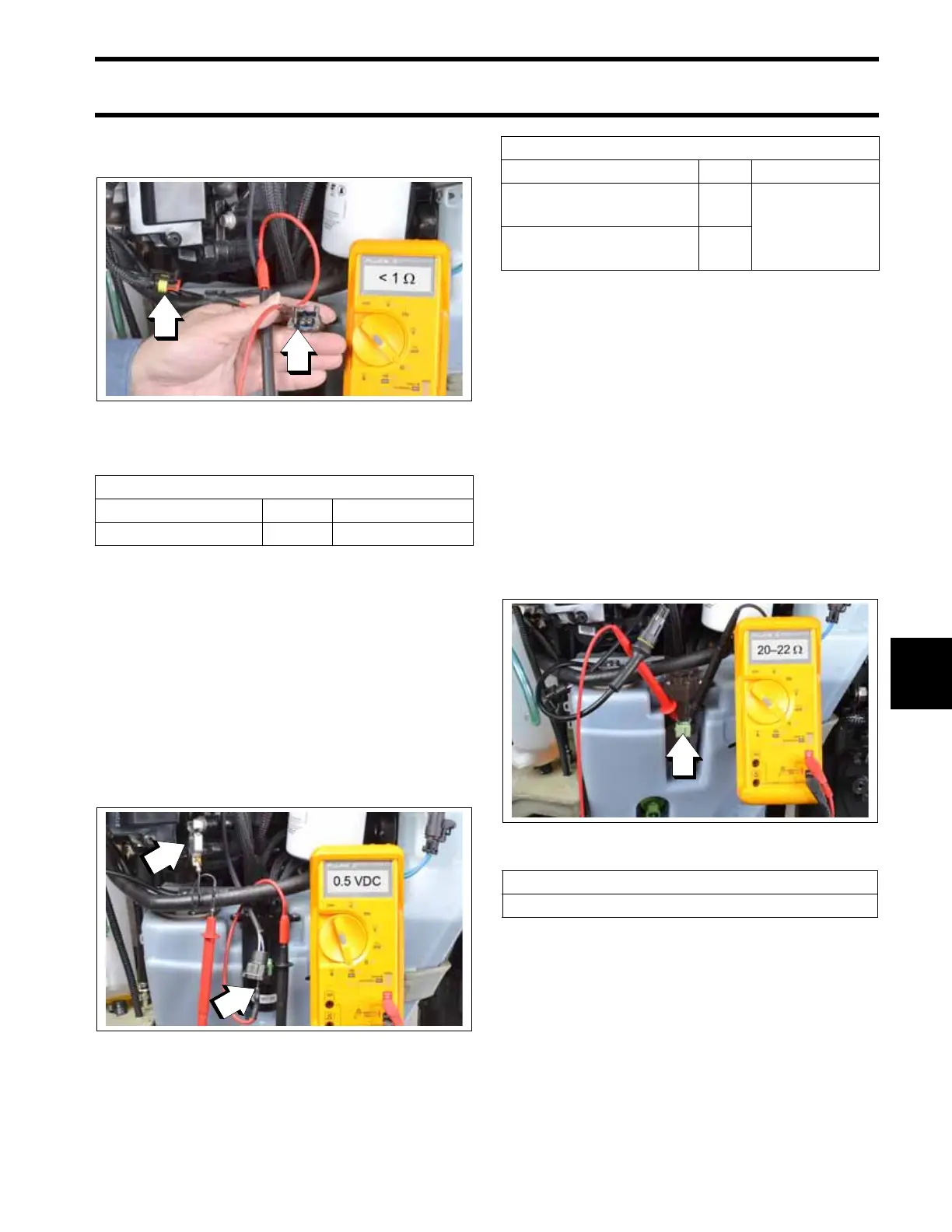
Oil Pump Resistance Test
Disconnect the battery cables at the battery. Dis-
connect the electrical connector from the oil
pump.
Use a digital multimeter with appropriate test
probe leads to measure the resistance between
the pins of the oil pump connector.
Results:
• An infinite reading (∞) indicates an open circuit
of the pump winding.
Replace faulty pump.
Oil Pump Connector
009230
1. Pin A, 55 V, red/white wire
2. Known good circuit (fuel injector shown)
Oil Pump 55V Circuit Resistance
Wire Pin Result
WHITE/RED A < 1 Ω
Oil Pump Connector
009229
1. Black meter lead to pin B, blue or blue/orange wire
2. Red meter lead to engine ground
Oil Pump Signal Circuit (Diode Test)
Wire Pin Result
BLUE
(Crankcase Oil Pump)
B
approximately
0.5 VDC
BLUE/ORANGE
(Cylinder Oil Pump)
B
1. Oil pump connector
009231
Oil Pump Resistance
20 to 22 Ω