125
Electrical and Ignition
Stator Tests
6
Stator Tests
The stator consists of 3 windings (6 poles each)
on a 7 inch diameter core and generates an out-
put voltage of 55 VAC (1700 watts maximum).
This voltage is converted by the EMM and pro-
vides 55 VDC for fuel injector, fuel and oil pump
operation. The ignition module of EMM is also
powered by the 55 VDC output.
Stator Resistance Tests
Use a digital multimeter with appropriate test
probe leads to check resistance of stator wind-
ings.
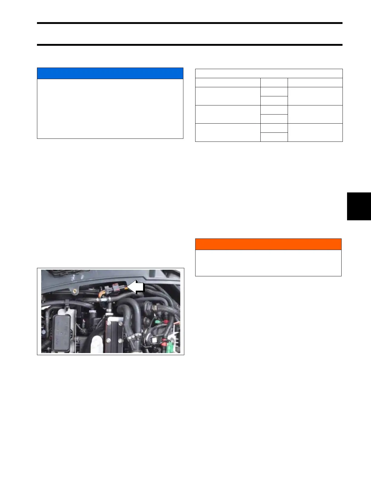
Disconnect the stator (6-pin) connector from the
engine harness (6-pin) connector.
Use an appropriate adapter to connect the meter
leads to the following pins of the stator connector:
IMPORTANT: A reading of less than 2 ohms is
acceptable. Make sure meter is calibrated to read
1 ohm or less.
Check for a grounded winding. Connect one
meter lead to ground and alternately connect the
other meter lead to each stator wire. Meter should
read no continuity. If meter reads continuity,
replace stator.
Stator Voltage Output Test
Use a voltmeter to check the stator output voltage.
Set meter to read 110 VAC output. Disconnect the
CPS.
Disconnect the stator (6-pin) connector from the
engine harness (6-pin) connector.
Connect Stator Test Adapter tool, P/N 5006211, to
the stator connector.
Connect meter leads to terminals of adapter tool.
With a fully charged battery, crank the outboard
(100 RPM minimum) and observe meter reading:
• 20 VAC at 100 RPM
• 30 VAC at 150 RPM
• 42 VAC at 200 RPM
• 52 VAC at 250 RPM
NOTICE
Use appropriate test leads or adapters such
as Test Probe Kit, P/N 342677, when perform-
ing electrical tests.
NEVER pierce the insulation of the engine
wiring, or use any piercing-style test probe.
Piercing insulation damages the wire and can
cause other unintended electrical problems.
1. Stator connector
009175
Stator Winding Resistance
Wire Pin Result
YELLOW
YELLOW/WHITE
1
0.512 ± 0.020 Ω
@ 73°F (23°C)
4
ORANGE
ORANGE/WHITE
2
0.512 ± 0.020 Ω
@ 73°F (23°C)
5
BROWN
BROWN/WHITE
3
0.512 ± 0.020 Ω
@ 73°F (23°C)
6
WARNING
To prevent accidental starting of outboard,
disconnect the crankshaft position sensor
(CPS).