365
Gearcase
Water Pump Service
14
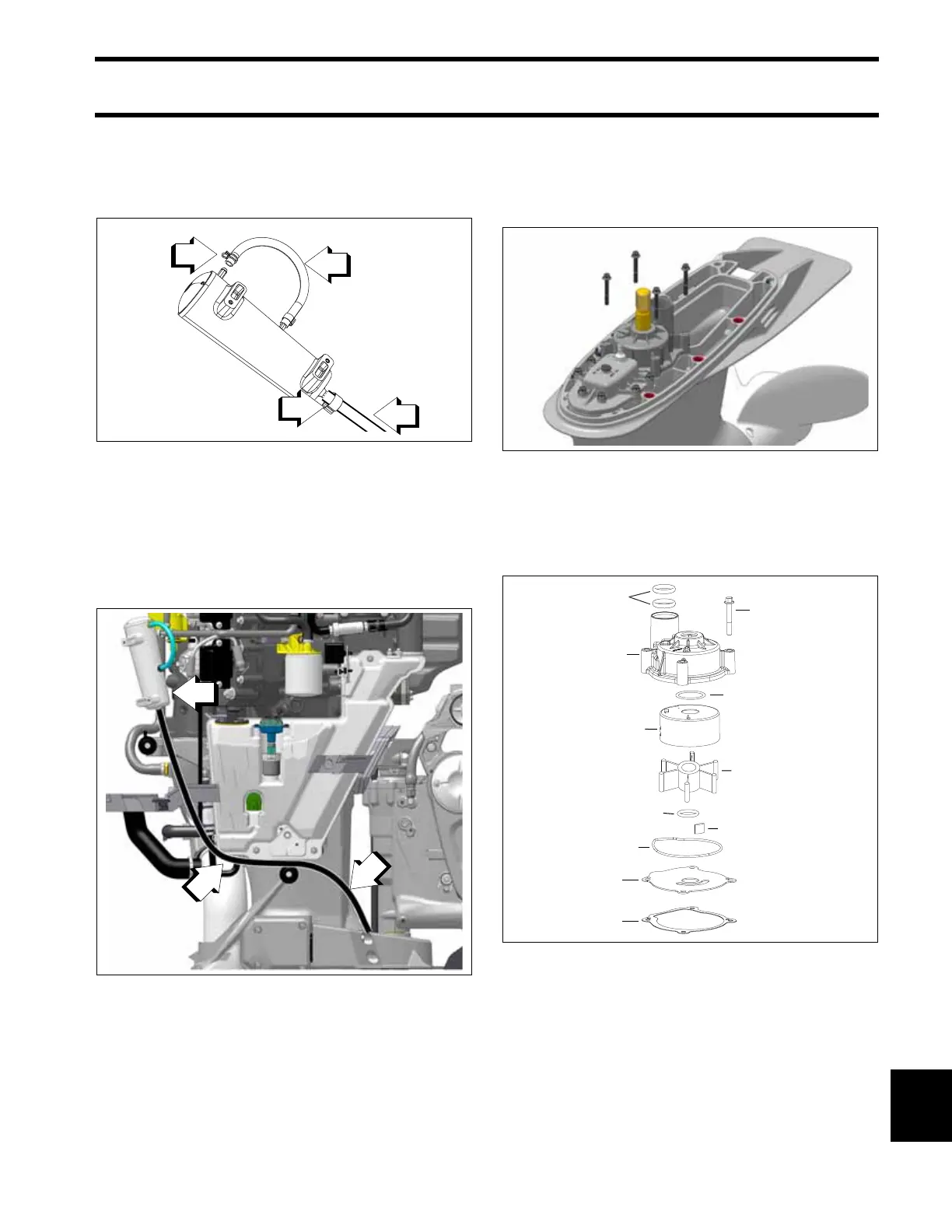
Install the oil reservoir vent hose to the top of the
oil reservoir, secure with spring clamp. Install the
oil hose on to the bottom of the oil reservoir with a
new 15.7 mm Oetiker clamp.
Route the oil reservoir hose from the gearcase to
the oil reservoir with a direct continuous rise as
shown. Do NOT allow low points. Any low points
will prevent the gearcase from venting properly.
Be sure to calibrate the shift actuator if installing a
new gearcase or shift actuator.
Install the frames and covers. Refer to Engine
Cover and Frame Service on p. 55.
Water Pump Service
Disassembly
Remove the four impeller housing screws.
Slide the water pump off the driveshaft. Remove
the impeller key, O-ring, impeller plate, and gas-
ket. Discard the gasket. Remove all the parts from
the housing.
1. Oil reservoir vent hose
2. Spring clamp
3. Oil hose
4. Oetiker clamp
5008933-15
1. Oil reservoir hose
2. Continuous rise
3. Oil reservoir
009328
5008933-16
1. Gasket
2. Plate
3. Housing seal
4. Key
5. O-ring
6. Impeller
7. Cup
8. Seal ring
9. Housing
10. Water tube o-rings
11. Screw (4X)
5008933-17