257
Powerhead
Powerhead Assembly
11
Use Driver, P/N 396747, to install the wrist pin
through the piston, pushing the bearing installer
out through the piston.
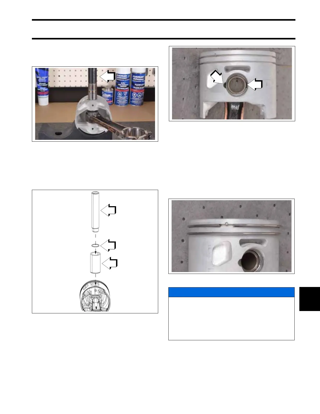
Use Wrist Pin Cone, P/N 331913, and Driver,
P/N 396747, to install new wrist pin retaining rings
in each wrist pin hole. Make sure the gap of each
retaining ring faces away from the notch in the pis-
ton.
Installing Pistons
When all pistons and connecting rods are assem-
bled, install piston ring sets. Be sure rings are
installed in the cylinder used to test ring end gap.
Refer to Powerhead Inspection on p. 251.
IMPORTANT: Be sure gap of ring fits squarely
around dowel pin.
Coat pistons, rings, cylinder walls, and ring com-
pressor with outboard lubricant.
Center connecting rod in piston and locate piston
rings on dowel pins. Place appropriate ring com-
pressor on piston.
1. Driver, P/N 396747
009700
1. Wrist Pin Cone, P/N 331913
2. Wrist pin retaining ring
3. Driver, P/N 396747
009707
1. Gap in retaining ring
2. Notch in piston
009701
009702
NOTICE
Before continuing, make sure that all Three-
bond sealant has been removed from the cyl-
inder block and crankcase mating flanges. If
traces of hardened sealant are left, main
bearings could be misaligned. Refer to Cylin-
der Block Cleaning on p. 250.