323
Stern and Swivel
Trim & Tilt System Service
13
Trim & Tilt System
Service
Trim & Tilt Manifold Service
Procedure
Disconnect the battery cables at the battery.
Remove the engine covers, port, starboard and
front frames. Refer to Engine Cover and Frame
Service on p. 55.
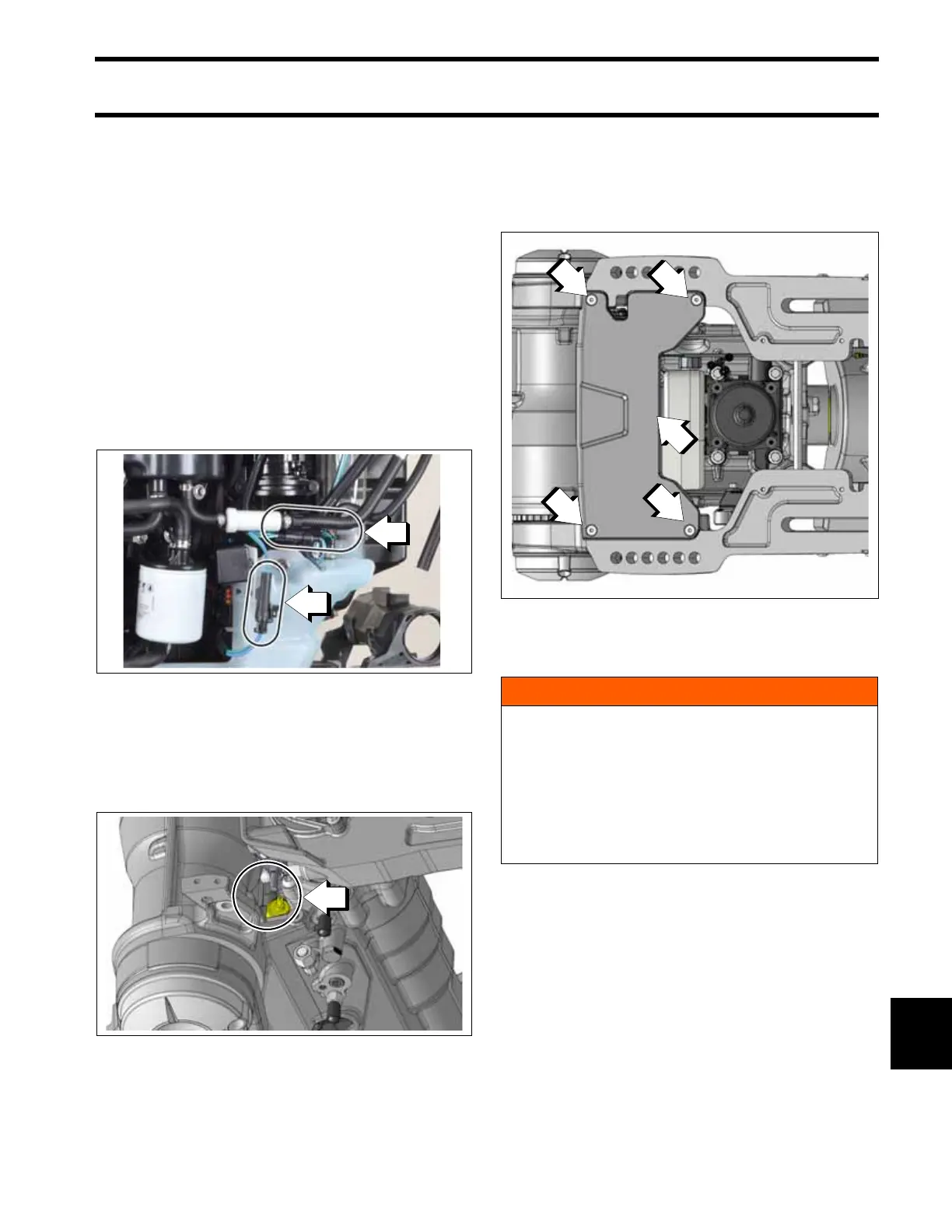
Disconnect the trim motor and trim sender electri-
cal connectors (starboard side).
Position electrical wiring to the port side of the
engine for removal. Wiring must pass through the
area shown. Do NOT attempt to remove wiring at
this time.
Outboard Removed from Boat
If the outboard is removed from the boat, remove
the four screws retaining the plate to the stern
brackets. Then remove the plate.
Outboard Installed on Boat
If the engine is installed on the boat, tilt the out-
board to the full tilt UP position.
1. Trim motor electrical connector
2. Trim sender electrical connectors
009171
1. Wiring pass-through area
009446
1. Screw
2. Plate
009448
WARNING
Support the outboard by the gearcase in the
UP position, with a suitable hoist.
When servicing the trim and tilt manifold, the
outboard will drop from the tilted position.
Avoid personal injury; always support the
outboard’s weight with a suitable hoist during
service.