203
Oiling System
Oiling System Tests
8
Connect the positive meter lead to the engine har-
ness connector wire listed in the table. Connect
the negative meter lead to engine ground.
Results:
• An infinite reading (∞) indicates an open circuit.
Isolate the faulty component. Check wiring and
connections. Repair or replace faulty wiring.
Oil Level Sender Resistance Test
Remove the electrical connector from the oil level
sender. Use a digital multimeter with appropriate
test probe leads to measure the resistance of the
oil level sender.
Results:
• An infinite reading (∞) indicates an open circuit.
Isolate the faulty component. Check wiring and
connections. Repair or replace faulty wiring.
Oil Level Sender Circuit Test
Remove the electrical connector from the oil level
sender.
Use the diode test function of a digital multimeter
to check the signal circuit.
Connect the BLACK meter lead to the wire listed
in the table, connect the RED meter lead to
engine ground.
Results:
• No reading (OL or ∞) indicates an open circuit.
• A reading of zero (0) indicates an short circuit.
Isolate the faulty component. Check wiring and
connections. Repair or replace faulty wiring.
Use a digital multimeter with appropriate test
probe leads to measure the resistance of the oil
level sender ground circuit.
Connect the positive meter lead to the engine har-
ness connector wire listed in the table. Connect
the negative meter lead to engine ground.
Results:
• An infinite reading (∞) indicates an open circuit.
Isolate the faulty component. Check wiring and
connections. Repair or replace faulty wiring.
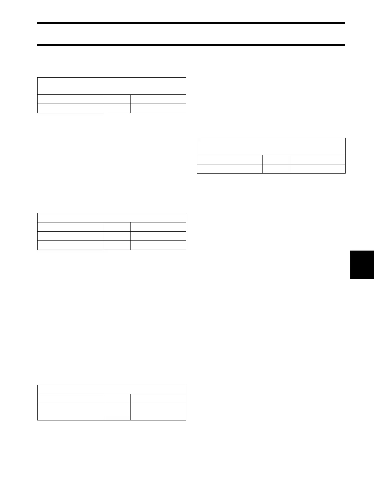
LOW OIL Switch
Ground Circuit Resistance
Wire Pin Result
BLACK 2 < 1 Ω
Oil Level Sender Resistance
Float Position Pin Result
Up (Full) – 30 Ω
Down (Empty) – 240 Ω
Oil Level Sender Circuit Diode Test
Wire Pin Result
PINK 1
approximately
0.5 VDC
Oil Level Sender
Ground Circuit Resistance
Wire Pin Result
BLACK/WHITE 2 < 1 Ω