131
Electrical and Ignition
Electric Starter Tests
6
Electric Starter Tests
Confirm the following BEFORE beginning any
tests on the starting system:
• Battery voltage at the battery is a minimum of
12 V.
• Turn key switch to the ON position, does the
fuel pump run?
•Yes, the remote control and EMM are ON.
•No, the EMM is OFF. Check remote control
network and connections. Check tether cord is
attached to emergency stop switch (second
station in dual station application).
• Check the remote control gear position indicator
LEDs. The remote control MUST be in NEU-
TRAL, the engine will NOT crank if in gear.
Starter Voltage Test
Use a digital multimeter to check battery voltage
at the battery. Crank the engine and record the
voltage.
Use a digital multimeter to check voltages at the
starter.
Connect the positive meter lead to the battery (B)
terminal on the starter. Connect the negative
meter lead to the ground terminal on the starter
housing.
Results:
• Recorded battery voltage ± 0.5 V: Readings are
GOOD.
• Less than recorded battery voltage: Check posi-
tive and negative cable connections at the
starter, center frame and at the battery.
Connect the positive meter lead to the start (S)
terminal on the starter. Connect the negative
meter lead to the ground terminal on the starter
housing. Crank the engine.
Results:
• Recorded battery voltage ± 0.5 V: Readings are
GOOD.
• Less than recorded battery voltage: Check 30 A
fuse and start relay.
Starter Voltage Drop Test
Use a digital voltmeter to measure the voltage
drop on each section of the start circuit.
STEP 1: Connect voltmeter positive (+) lead to
the terminal for the negative (–) battery cable at
the starter. Connect voltmeter negative (–) lead to
negative (–) battery post.
• Activate the starter motor and record the volt-
age reading.
STEP 2: Connect positive (+) lead to battery posi-
tive (+) terminal. Connect negative (–) lead to
starter solenoid “B” terminal.
• Activate the starter motor and record the volt-
age reading.
WARNING
To prevent accidental starting of outboard,
disconnect crankshaft position sensor (CPS).
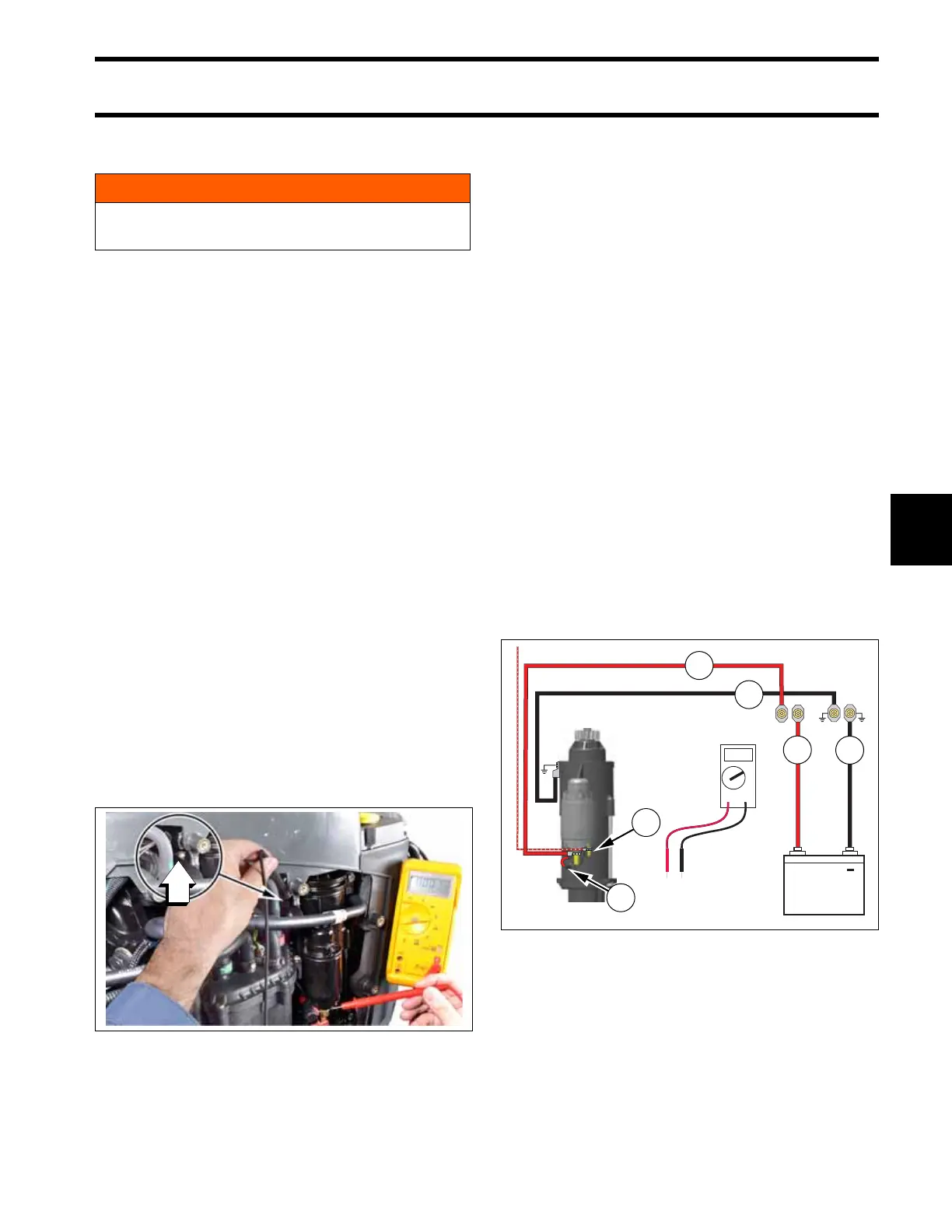
1. Ground terminal on the starter housing
009380
1. Negative battery cable (battery to rigging center)
009338
2. Negative battery cable (rigging center to starter housing)
3. Positive battery cable (battery to rigging center)
4. Positive battery cable (rigging center to solenoid “B” terminal)
5. Solenoid “S” terminal
6. Starter cable