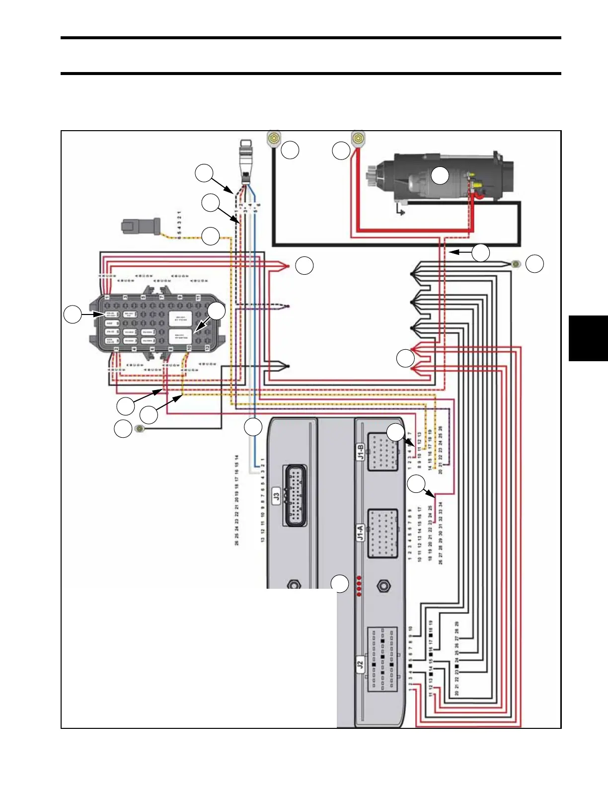
1. Negative Battery Cable
2. Main Harness Grounds
3. Positive Battery Cable
4. Red Wire: 12 Volts to EMM & Fuse Panel
5. Red/Purple Wire: Fused B+
6. Fuse (Starter Solenoid)
7. Starter Relay
8. Red/Yellow Wire: Fused 12V to Remote Control
9. Black/White Wire: System “Wake Up” Signal
10. White & Blue Wires: CANbus Signals (Start Signal From Helm)
11. Yellow/Red Wire: Neutral Signal from Shift Actuator
12. EMM
13. Yellow/Red Wire: Start Signal from EMM to Start Relay
14. Red/Tan Wire: Start Signal from Start Relay to Starter Solenoid
15. Starter Solenoid & Starter Motor Assembly