Stern and Swivel
Stern & Swivel Bracket
344
Trim Sender Service
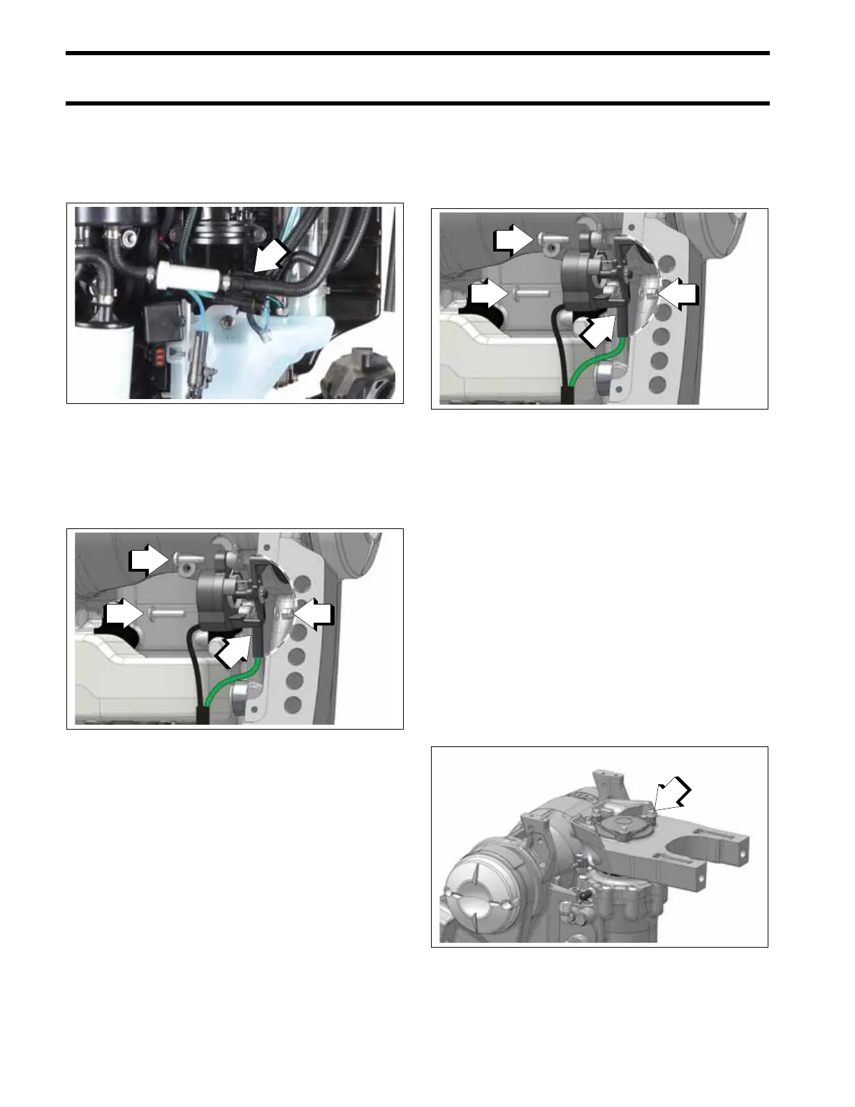
Removal
Disconnect the trim sender electrical connector.
Remove the nut, washer and ring terminal from
the lower screw.
Then remove both screws and the trim sender
from the swivel bracket.
Installation
Position the trim sender on the swivel bracket.
Loosely install the upper screw to keep the trim
sender in position.
Install the lower screw into the trim sender and
through the boss on the swivel bracket.
Apply No-Ox Grease, P/N 768230 to the ring ter-
minal. Then install the ring terminal over the lower
screw. Install the washer and nut on the lower
screw.
Tighten both screws to a torque of 22 to 30 in. lbs.
(2.5 to 3 N·m).
Apply No-Ox Grease, P/N 768230 over the ring
terminal, washer and nut.
Steering Arm, End Cap and Lower
Bracket Service
Removal
The engine must be removed from the stern and
swivel bracket assembly to complete these proce-
dures. Refer to Removal on p. 334. Removal of
the stern and swivel bracket from the boat for
these procedures is optional.
Steering Arm Removal
Remove the three screws from the steering arm
cover.
1. Trim sender electrical connectors
009171
1. Nut and washer
2. Ring terminal
3. Screws
009466
1. Upper screw
2. Lower screw
3. Ring terminal
4. Washer and nut
009466
1. Screws
009644