188
Oiling System
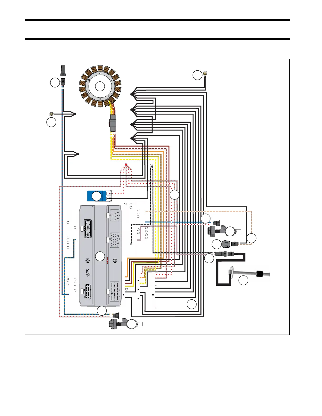
Oiling System Circuit Diagram
Oiling System Circuit Diagram
J2
J1-B
J1-A
J3
J4
A B
1 2 3 4 5 6 7
8 9 10 11 12 13
14 15 16 17 18 19
20 21 22 23 24 25 26
1 2 3 4 5 6 7 8 9 10
11 12 13 14 15 16 17 18 19
20 21 22 23 24 25 26 27 28 29
16 15 14 13 12 11 10 9
8 7 6 5 4 3 2 1
1 2
1 2
26 25 24 23 22 21 20 19 18 17 16 15 14
13 12 11 10 9 8 7 6 5 4 3 2 1
1 2 3 4 5 6 7 8 9
10 11 12 13 14 15 16 17
18 19 20 21 22 23 24 25
26 27 28 29 30 31 32 33 34
A B
9
10
11
2
6
7
8
1
3
4
5
14
13
5
5
009247
12
1.
2.
3.
4.
5.
6.
7.
Stator
EMM
Capacitor
55 V Circuit (WHITE/RED)
Grounds, NEG (BLACK)
Crankcase Oil Pump
Crankcase Oil Pump control (BLUE)
8.
9.
10.
11.
12.
13.
14.
Cylinder Oil Pump
Cylinder Oil Pump control (BLUE/ORANGE)
LOW Oil Switch
LOW OIL Signal (TAN/WHITE)
Oil Level Sender
Oil Level Signal (PINK)
Remote Oil Pump Electrical Connector