Electrical and Ignition
Electrical Harness Connections
112
Electrical Harness Con-
nections
Inspect wiring and electrical connections. Disas-
semble and clean all corroded connections.
Replace damaged wiring, connectors, or termi-
nals. Repair any shorted electrical circuits. Refer
to wiring diagrams and reference charts for spe-
cific wiring details.
Refer to Connector Servicing on p. 139.
Engine Harness to Stator
Connector
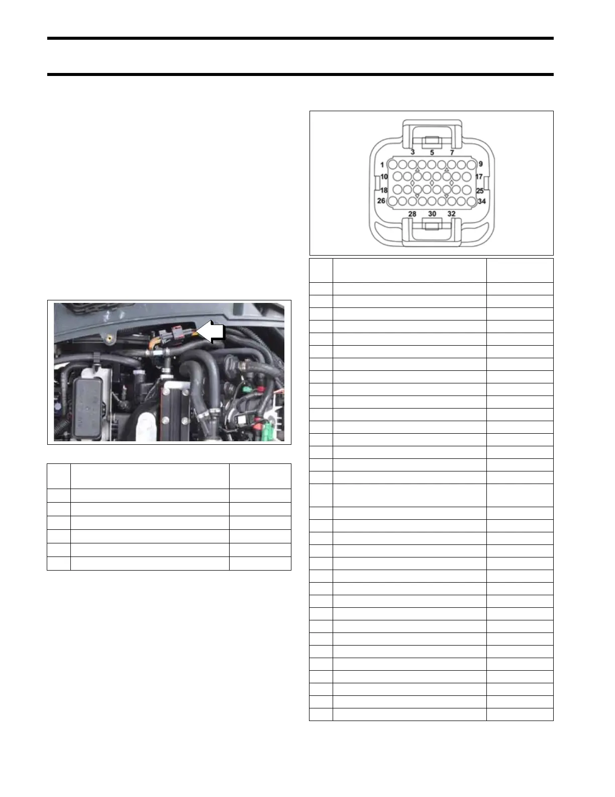
EMM J1-A Connector
009175
Pin
No.
Description of Circuit Wire Color
1 Stator winding (1S) Yellow
2 Stator winding (3S) Orange
3 Stator winding (2S) Brown
4 Stator winding (1F) Yellow /White
5 Stator winding (3F) Orange/White
6 Stator winding (2F) Brown/White
Pin
No.
Description of Circuit Wire Color
1Trim send IN White/Tan
2 Manufacturing connector Red
3 Manufacturing connector White
4 Trim sender bond Dark Green
5 Manufacturing connector Black
6 Crankshaft position sensor (CPS) Yellow
7 Ground, CPS (digital) Yellow/White
8 Key Switch (Bootstrap) Blk/Orange
9 Stop circuit Blk/Yellow
10 ETB, +5 V Red/White
11 ETB, Ground (analog) Black/White
12 Engine temperature sensor, port Pink/Black
13 Ground (analog) Black/White
14 Shift Actuator, Ground (analog) Black/White
15 Water pressure, +5 V Pink
16 Ground (analog) Black/White
17 Engine temp sensor, Starboard
Ground (analog)
Black/White
18 TPS A Green/Yellow
19 Engine temp sensor, starboard Pink/Black
20 Air temperature sensor Pink/Blue
21 Water in Fuel Pink/Green
22 Oil level sender Pink
23 Fused +12 V Red/Purple
24 empty
25 empty
26 TPS B Green/Orange
27 Shift Actuator +5 V Red/White
28 Water pressure +5 V Red/White
29 Shift actuator positive Yellow/Black
30 Trim sender +5 V Red/White
31 empty
32 empty
33 empty
34 empty