113
Electrical and Ignition
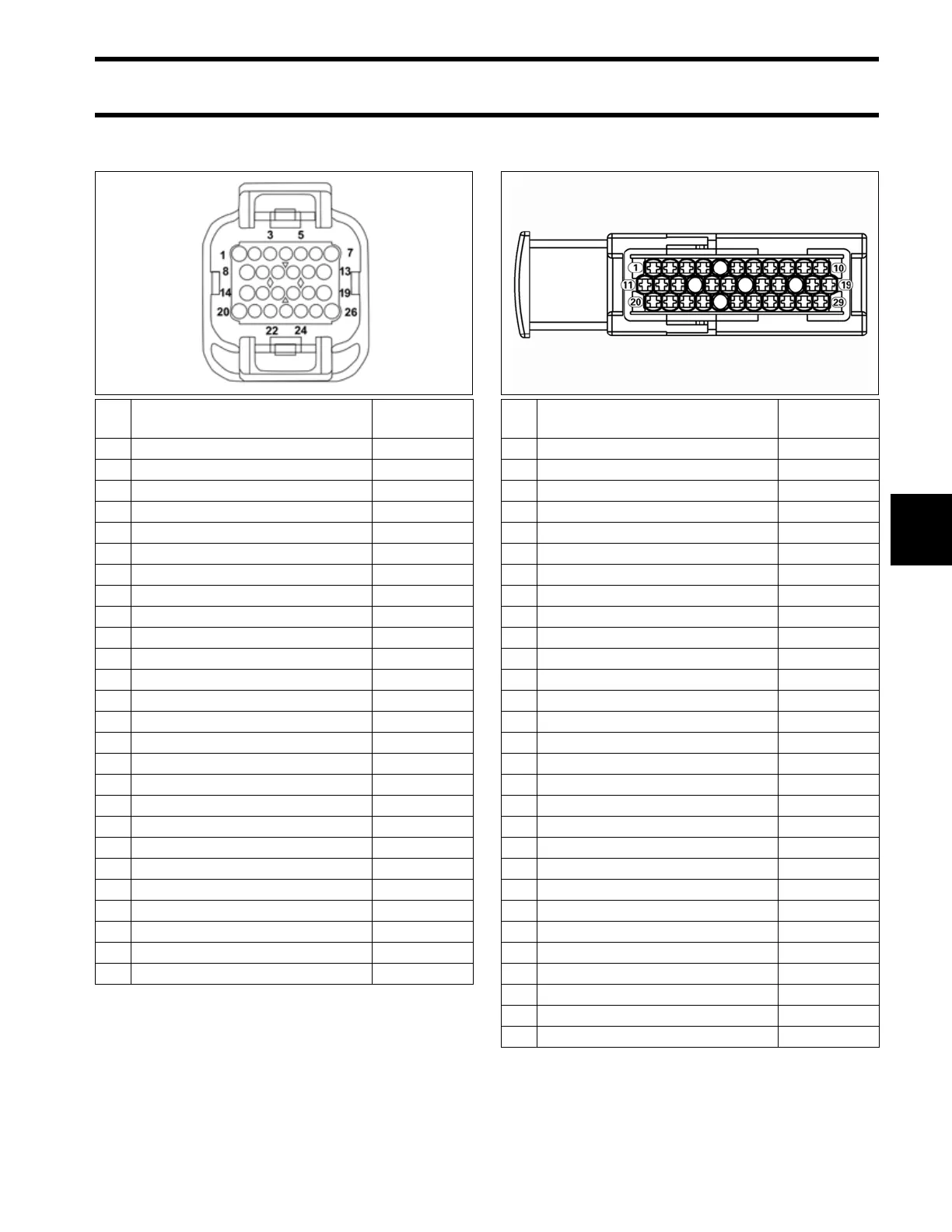
Electrical Harness Connections
6
EMM J1-B Connector
EMM J2 Connector
Pin
No.
Description of Circuit Wire Color
1 Injector, cylinder 3 Purple
2 Injector, cylinder 5 Green
3 Fused B+ (12V) Red/Purple
4 Trim UP signal to trim relay Blue/White
5 Trim DOWN signal to trim relay Green/White
6 Ignition, cylinder 3 Orange/Purple
7empty
8 Injector, cylinder 1 Blue
9 Trim switch, UP Blue/Black
10 Trim switch, DOWN Green/Black
11 Shift actuator, neutral feedback Yellow/Red
12 empty
13 empty
14 EMM signal to start relay Yellow/Red
15 empty
16 empty
17
18 Fused B+ (12V) to 55V relay Purple/Yellow
19 Ignition, cylinder 1 Orange/Blue
20 Oil pump, crankcase Blue
21 Switched B+ (12V), wake-up Purple/Black
22 empty
23 Low oil switch Tan/White
24 Fuel level, upper Brown/Orange
25 Ignition, cylinder 5 Orange/Green
26 Fuel level, lower Brown/Blue
Pin
No.
Description of Circuit Wire Color
1B+ Red
2B+ Red
3 Isolated B+ Red/Black
4 Battery ground Black
5 Battery ground Black
6empty
7 Winding 1S Yellow
8 Winding 2S Brown
9 Injector, generator ground Black
10 Winding 3S Orange
11 B+ Red
12 B+ Red
13 Isolated B+ Red/Black
14 Battery ground Black
15 Battery ground Black
16 Battery ground Black
17 Winding 1F Yellow/White
18 Winding 3F Orange/White
19 +55V White/Red
20 empty
21 Isolated B+ Red/Black
22 Isolated B+ Red/Black
23 Battery ground Black
24 Battery ground Black
25 Battery ground Black
26 empty
27 Injector, generator ground Black
28 Winding 2F Brown/White
29 +55V White/Red