305
Stern and Swivel
DPS System Tests
13
Steering Motor Circuits
Use the diode test function of a digital multimeter
to check the steering motor circuit.
Connect the meter leads as listed in the table
below.
Results:
• Readings as listed in table indicate circuit is
good.
• No reading (OL or ∞) indicates an open circuit.
• A reading of zero (0) indicates an short circuit.
Replace faulty module.
Steering Sensor Circuits
Use the diode test function of a digital multimeter
to check the signal circuit.
Connect the BLACK meter lead to the wire listed
in the table, connect the RED meter lead to
engine ground.
Results:
• Readings as listed in table indicate circuit is
good.
• No reading (OL or ∞) indicates an open circuit.
• A reading of zero (0) indicates an short circuit.
Replace faulty module.
CANbus Circuit
Use a digital multimeter with appropriate test
probe leads to measure sensor circuit resistance.
Connect the positive meter lead to the DPS Mod-
ule connector/ wire listed in the table.
Connect the negative meter lead to engine
ground.
Results:
• No reading (OL or ∞) indicates an open circuit.
• A reading of zero (0) indicates an short circuit.
Replace faulty module.
Steering Pressure Sensor Tests
Use Evinrude Diagnostics software v 6.1 or higher
to observe Port Pressure and Starboard Pressure.
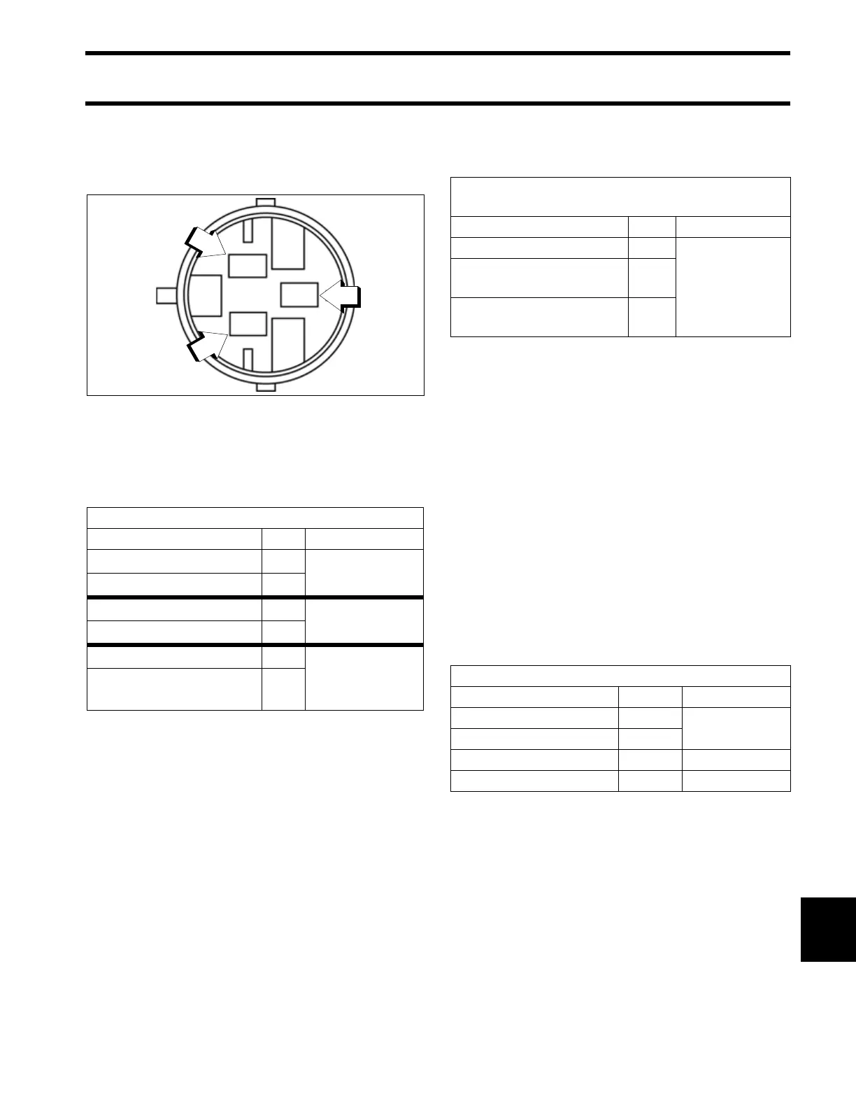
Steering Motor Connector
009403
1. Pin 1 (lower, Module B+)
2. Pin 2 (upper, Motor B+)
3. Pin 3 (middle, black wire)
DPS Motor Circuit (Diode Test)
Meter Lead Pin Result
Positive meter lead to: 2
approximately
0.5 VDC
Negative meter lead to: 1
Negative meter lead to: 2
open load
Positive meter lead to: 1
Negative meter lead to: 3
2.43 VDC
Positive meter lead to:
Engine ground
–
DPS Module Sensor Circuits
(Diode Test)
Connector/Wire Pin Result
Steering Position/ Blue 2
approximately
0.5 VDC
Pressure Sensor 2
/ Green
B
Pressure Sensor 1
/ White
B
CANbus Circuit Resistance Test
Connector/Wire Pin Result
CAN (Orange/Black) 1
120 Ω
CAN (Brown/Orange) 2
CAN (Purple/White) 3 N/A
CAN (Black) 4 <1 Ω