Electrical and Ignition
Tilt/Trim Relay Test
132
STEP 3: Connect positive (+) lead to starter sole-
noid terminal. Connect negative (–) lead to oppo-
site starter solenoid terminal.
• Activate the starter motor and record the volt-
age reading.
STEP 4: Connect positive (+) lead to starter cable
of solenoid terminal. Connect negative (–) lead to
starter motor terminal.
• Activate the starter motor and record the volt-
age reading.
Results:
If the voltage reading from any step is greater than
0.5 VDC check that connections are clean, tight
and free of corrosion. Clean or replace any cor-
roded or damaged cables or connections.
Tilt/Trim Relay Test
The tilt and trim (TNT) module contains the cir-
cuitry and relays required for power trim and tilt
operation.
The tilt and trim switch provides B+ input to
green/white or blue/white wire of the TNT module.
Operation
The relay activates when B+ input from the switch
is supplied to terminal 86 of the internal relays.
Terminal 87a connects to ground (B–).
Terminal 87 connects to B+.
Terminal 30 connects TNT motor.
Terminals 87a and 30 are connected when relay is
not activated. This supplies ground (B–) connec-
tion to TNT motor.
Terminals 87 and 30 are normally open. B+ is
applied to terminal 30 when relay is activated.
This supplies B+ connection to TNT motor.
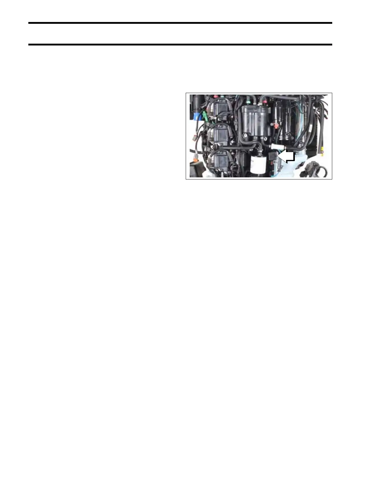
Refer to Tilt and Trim Module Diagram.
1. Tilt and trim module
009186