Engine and Control Systems
Engine Management Module (EMM)
78
Engine Management
Module (EMM)
The Engine Management Module (EMM) is a
water-cooled controller. It controls engine man-
agement and engine–related remote control func-
tions.
This section discusses the functions of the EMM
and its various internal and external sensors. It
also describes using Evinrude Diagnostics soft-
ware to retrieve and adjust service information
saved in the EMM.
EMM Functions
The EMM controls the following processes and
functions:
• Alternator output; 55 V and 12 V
• Start Assist Circuit (SAC) voltage boost
• Fuel and ignition timing and duration
• Fuel injector activation
• Oil pump activation
• Electric fuel lift pump control
• Electric high pressure fuel pump control
• Idle speed control
• RPM limiter
• Electrical circuit monitoring
• Fault code creation and storage
• Warning system activation
• ROM verification, self-test
• Cold starting
• Output of diagnostic data
• Tachometer signal
• RPM profile and engine hours
• Oil pump activation
• Anti-knock compensation
• Electronic throttle control
• Electronic shift control
• Dynamic Power Steering
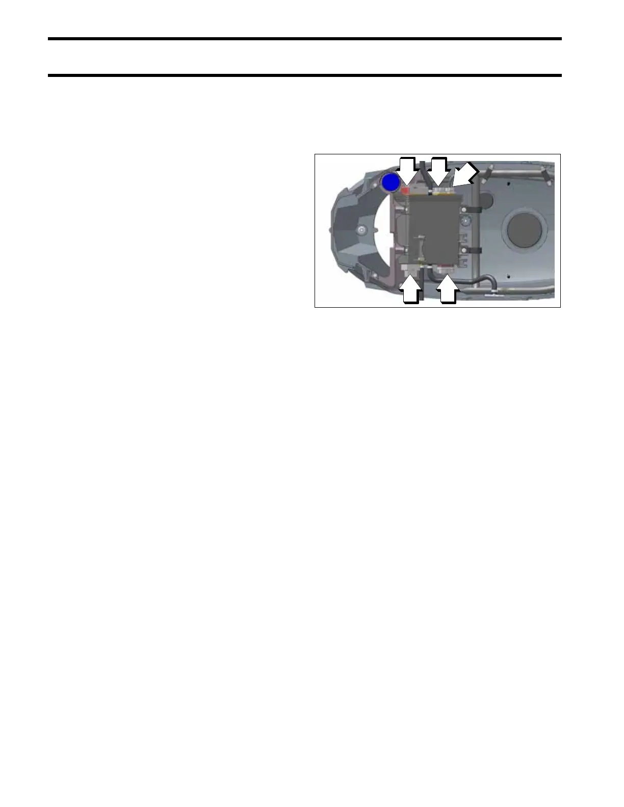
EMM Connections
IMPORTANT: EMM connections and wiring
must be clean and tight. Improper electrical con-
nections can damage the EMM. DO NOT run the
outboard with loose or disconnected wiring.
Make sure EMM connections are clean and tight.
• Engine wire harness to EMM connectors; J1-A,
J1-B, J2, J3, J4.
• Stator to EMM connections; one 6-pin AMP and
J2 connector.
EMM Inputs and Outputs Diagram
1. J1-A connector
2. J1-B connector
3. J2 connector
4. J3 connector
5. J4 connector
009332
1. EMM
2. 12 VDC Battery
3. Fuel Vapor Separator
4. Electronic Throttle Body
5. Shift Actuator
6. Knock Sensor (2)
7. Engine Temperature Sensor (2)
8. Exhaust Temperature Sender
9. Engine Oil Level Sender
10.Trim Sender
11.(reserved for future use)
12.DPS Pressure Sensors
13.Digital Remote Control
14.Intake Air Temperature Sensor
15.Crankshaft Position Sensor
16.Water in Fuel Sensor
17.Stator
18.Low Oil Switch
19.Trim Switch
20.(reserved for future use)
21.Fuel Injector (6)
22.Ignition Coil (6)
23.Water Valve
24.Digital Displays & Gauges
25.Dynamic Power Steering Module
26.Oil Pumps
27.Starter Solenoid & Motor
28.Trim & Tilt Relay
29.Vapor Vent Solenoid