369
Gearcase
Shift Actuator
14
Shift Actuator
Control Circuit Tests
Circuit tests check the integrity of the main engine
harness and EMM circuits using resistance or
diode tests. Continuity tests check the integrity of
ground circuits and/or the 55V circuit. These tests
eliminate the need to disconnect the engine har-
ness from the EMM, or remove the EMM.
Remove the electrical connector from the shift
actuator.
Make sure the key switch is OFF.
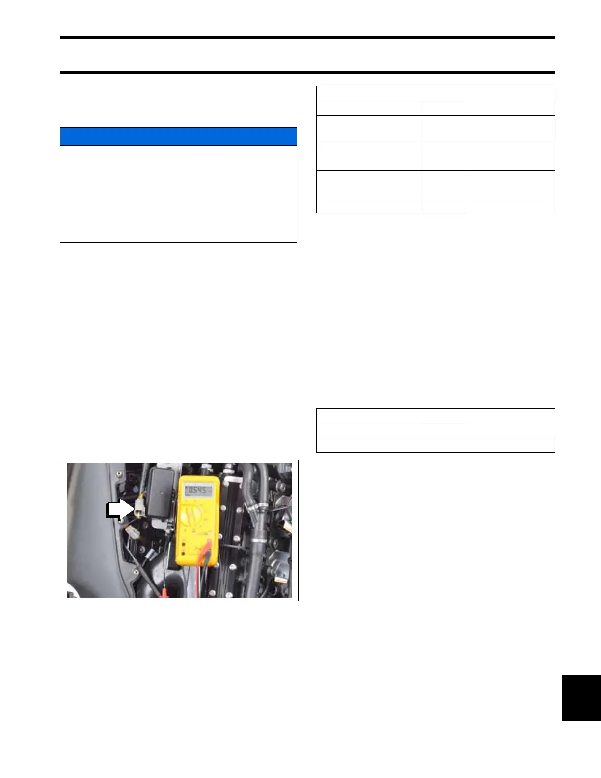
Use the diode test function of a digital multimeter
to check the shift actuator circuits. Use an appro-
priate test probe lead to connect the negative
meter lead to the wire listed in the table, connect
the positive meter lead to an engine ground.
Results:
• No reading (OL or ∞) indicates an open circuit.
• A reading of zero (0) indicates an short circuit.
Isolate the faulty component. Check wiring and
connections. Repair or replace faulty wiring.
Shift Actuator Ground Circuit
Use a digital multimeter with appropriate test
probe leads to measure the ground circuit resis-
tance. Connect the positive meter lead to the
engine harness connector wire listed in the table.
Connect the negative meter lead to engine
ground.
Results:
An infinite reading (
∞) indicates an open circuit.
Isolate the faulty component. Check wiring and
connections. Repair or replace faulty wiring.
Neutral Circuit
There are no tests for the neutral circuit.
NOTICE
Use appropriate test leads or adapters such
as Test Probe Kit, P/N 342677, when perform-
ing electrical tests.
NEVER pierce the insulation of the engine
wiring, or use any piercing-style test probe.
Piercing insulation damages the wire and can
cause other unintended electrical problems.
1. Engine harness connector (shift actuator)
009377
Shift Actuator Circuit Diode Test
Wire Pin Result
Yellow/Blue
1
approximately
0.5 VDC
Yellow/Green
2
approximately
0.5 VDC
Red/White
3
0.11 to 0.125
VDC
Yellow/Black 4 2.1± 0.5 VDC
Shift Actuator Ground Circuit Resistance
Wire Pin Result
Black/White 5 < 1 Ω