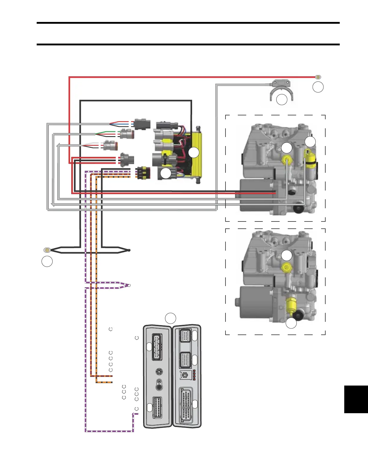
EasyManua.ls Logo

BRP Evinrude E-TEC G2 - DPS Electrical Circuit Diagram

BRP Evinrude E-TEC G2
460 pages
Print Icon
To Next Page IconTo Next Page
To Previous Page IconTo Previous Page
Loading...
303
Stern and Swivel
Dynamic Power Steering (DPS)
13
DPS Electrical Circuit Diagram
J2
J4
J3
J1-A
J1-B
SPLICE #9
BAT_GND
4X, AB
SPLICE #43
12V
21A, B, C
16 15 14 13 12 11 10 9
8 7 6 5 4 3 2 1
26 25 24 23 22 21 20 19 18 17 16 15 14
13 12 11 10 9 8 7 6 5 4 3 2 1
%
$
&
%
$
&
5
4
2
6
7
8
9
1
3
10
DPS – 2
DPS – 1
009734
1. EMM
2. DPS Module
3. DPS Module to EMM Connections
4. Steering Position Sensor (DPS - 2 models only)
5. Battery Post (B+ supply to DPS Module)
6. Port Steering Pressure Sensor (DPS - 2 only)
7. Starboard Steering Pressure Sensor (DPS - 2 only)
8. Helm Pressure Sensor (DPS - 1 only)
9. Pump Pressure Sensor (DPS - 1 only)
10. Ground (to port engine ground screw)

Table of Contents

Other manuals for BRP Evinrude E-TEC G2

Related product manuals