345
Stern and Swivel
Stern & Swivel Bracket
13
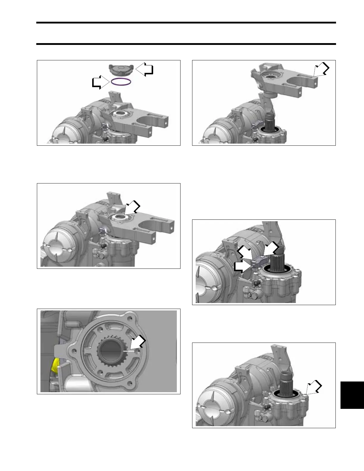
Remove the cover and o-ring
Use Spanner Socket, P/N 359224, to remove the
spanner nut.
Remove the locking washer. Then make an align-
ment mark on the splined steering shaft and steer-
ing arm to aid re-assembly.
Remove the steering arm from the steering shaft.
End Cap Removal
Remove the steering arm from the steering shaft.
Refer to Steering Arm Removal on p. 344.
Remove the two screws retaining the steering
position sensor, and remove the steering position
sensor.
Use a T-40 Torx driver to remove the eight screws
retaining the end cap assembly.
1. Cover
2. O-ring
009645
1. Spanner nut
009646
1. Alignment mark
009655
1. Steering arm
009647
1. Screws
2. Steering Position Sensor
009648
1. Screws
009648