Electrical and Ignition
Charging System Tests
128
55 V Alternator Circuit
Check battery ground cable for continuity.
With the key switch ON, check battery voltage at
battery (12 V).
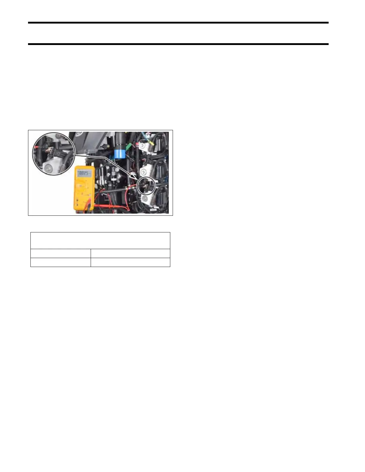
Then, use Electrical Test Probe Kit, P/N 342677,
and a digital multimeter set to read 55 VDC to
check voltage on white/red wires at an ignition coil
or fuel injector electrical connector.
With outboard running at 1000 RPM, voltage on
white/red wires should increase to 55 V. Voltage
readings at a specific speed (RPM) should be
steady.
If there is any other reading, refer to Stator Tests
on p. 125. Inspect the stator wiring and connec-
tions. Inspect the capacitor wiring, connections,
and capacitor. Repair the wiring or replace a faulty
capacitor, stator, or EMM.
1. 55V circuit (Ignition coil connector)
009370
Acceptable Alternator
Circuit Test Readings
Key switch ON approximately 30 VDC
Engine running approximately 55 VDC