Electrical and Ignition
Ignition System
124
Connect the negative meter lead to the red/white
wire of a known good circuit such as a fuel injec-
tor.
Results:
• An infinite reading (∞) indicates an open circuit.
Isolate the faulty component. Check wiring and
connections. Repair or replace faulty wiring.
Ignition Ground Circuit Resistance Test
Use a digital multimeter with appropriate test
probe leads to measure the ground circuit resis-
tance.
Make sure the key switch is in the OFF position.
Connect the positive meter lead to the engine har-
ness connector wire listed in the table. Connect
the negative meter lead to engine ground.
Results:
• An infinite reading (∞) indicates an open circuit.
Isolate the faulty component. Check wiring and
connections. Repair or replace faulty wiring.
Ignition Control Circuit Voltage Test
Disconnect the electrical connector from the igni-
tion coil.
Use a digital multimeter with appropriate test
probe leads to measure signal circuit voltage.
Connect the positive meter lead to the engine har-
ness connector wire listed in the table. Connect
the negative meter lead to engine ground. Turn
the key switch to the ON position.
Capacitor Test
IMPORTANT: Make sure the capacitor is dis-
charged before testing.
Disconnect the capacitor from electrical harness.
Use an ohmmeter set on the high ohms scale to
test the capacitor. Connect the meter leads to the
capacitor terminals:
• If the capacitor is working correctly, it will store
energy from the meter. The resistance reading
will increase until it goes to (nearly) infinity.
• If the capacitor is shorted, the reading will
immediately show full continuity.
• If there is an open circuit in the capacitor, the
meter will show no continuity.
If the resistance reading starts as a negative num-
ber, or the reading goes down in value, the capac-
itor already retains some stored energy. Ground
the capacitor and test again.
Ignition 55V Circuit Resistance
Wire Pin Result
WHITE/RED 3 < 1 Ω
Ignition Ground Circuit Resistance
Wire Pin Result
BLACK 1 < 1 Ω
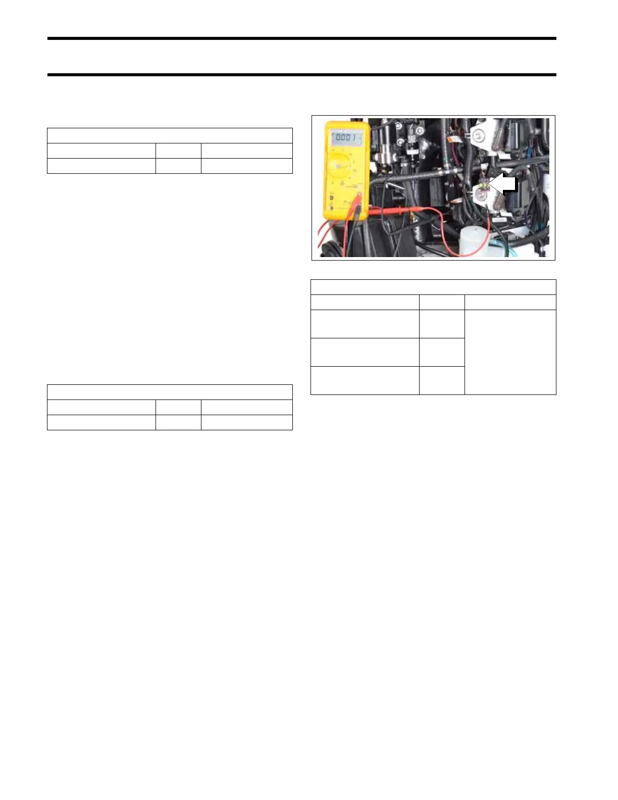
1. Engine harness connector (ignition coil)
009358
Ignition Circuit Voltage
Wire Pin Result
ORANGE/BLUE
(upper cylinder)
2
5 to 7 VDC
ORANGE/PURPLE
(middle cylinder)
2
ORANGE/GREEN
(lower cylinder)
2