137
Electrical and Ignition
Timing Adjustments
6
2. Record the degrees ATDC on the flywheel
directly across from the pointer.
3. Rotate the flywheel clockwise until the piston
contacts the tool.
4. Record the degrees BTDC on the flywheel
directly across from the pointer.
5. Add the number of degrees recorded in step 2
to the number of degrees recorded in step 4 to
obtain the degree Range.
Then divide the Range by 2 to obtain the
Result.
6. With the piston against the tool, adjust the
pointer to read the result from Step 5.
7. – Rotate the flywheel counterclockwise until
the piston contacts the tool. Record the
degrees ATDC on the flywheel.
– Rotate the flywheel clockwise until the pis-
ton contacts the tool. Record the degrees
BTDC on the flywheel.
– The timing pointer is correctly centered when
the piston contacts the tool at the Step 5 result,
at both the ATDC and BTDC positions.
8. Rotate the flywheel counterclockwise slightly
to release tool then remove it from spark plug
hole.
Install the spark plugs. Refer to Spark Plugs on
p. 22.
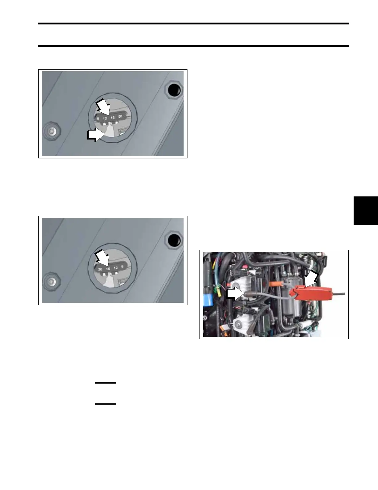
Install Timing Lead, P/N 587316, onto the #1 cyl-
inder coil and spark plug as shown. Connect the
timing light pick up to the timing lead.
IMPORTANT: Keep the timing light pick up a
minimum of 2 inches (51 mm) away from the igni-
tion coil during the timing verification procedure.
1. Timing pointer
2. Record the degrees on the flywheel
009365
1. Record the degrees on the flywheel
009366
Example:
14° ATDC
+16° BTDC
Range 30°
÷ 2
Result 15°
1. Timing Lead, P/N 587316
009364
2. Timing light pick up a minimum of 2 inches (51 mm) away from
the ignition coil