199
Oiling System
Oiling System Tests
8
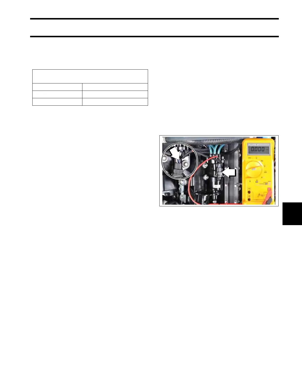
Check the control signal while the Oil Injector test
is running. Set the digital multimeter to the fre-
quency setting or the Hertz (Hz) scale.
• Meter should read 130 to 150 Hz.
Results:
• If voltage and control signal readings at pin B
are within range, the EMM and wiring are not at
fault.
• If voltage at pin B is not within range, check volt-
age at pin A (white/red wire) of oil pump electri-
cal connector.
Connect positive meter lead to pin A (white/red
wire) of oil pump electrical connector. Observe
voltage at pin A.
• Voltage at pin A should be approximately 30 V.
Start the engine. Observe voltage at pin A.
• The voltage at pin A should be approximately
55 V.
Results:
• If voltage is not within range, refer to Oil Pump
Circuit Tests on p. 200, and Oil Pump Resis-
tance Test on p. 201.
• No voltage reading should result in Code 34;
Crankcase Oil Pump Open Circuit. Refer to
System Voltage Test on p. 122.
Cylinder Oil Pump
The EMM controls the pump by providing ground
through pin 10 (blue/orange wire) of the J3 con-
nector and pin B (blue/orange wire) of the oil
pump connector.
Use a digital multimeter calibrated to a scale that
reads 55 V (DC) to measure voltage between the
oil pump electrical connector and engine ground.
Connect negative meter lead to ground.
Use an appropriate test probe lead to connect
positive meter lead to pin B (blue/orange wire) of
oil pump electrical connector.
Turn the key switch to the ON position. Observe
voltage at pin B.
• Voltage at pin B should be approximately 30 V.
Acceptable Oil Pump
Test Readings
Key switch ON approximately 30 VDC
Control signal 130 to 150 Hz
Engine running approximately 55 VDC
1. Oil pump
2. Pin B (blue/orange wire)
009246