CDM-625A Advanced Satellite Modem MN-CDM625A
Introduction Revision 4
1–12
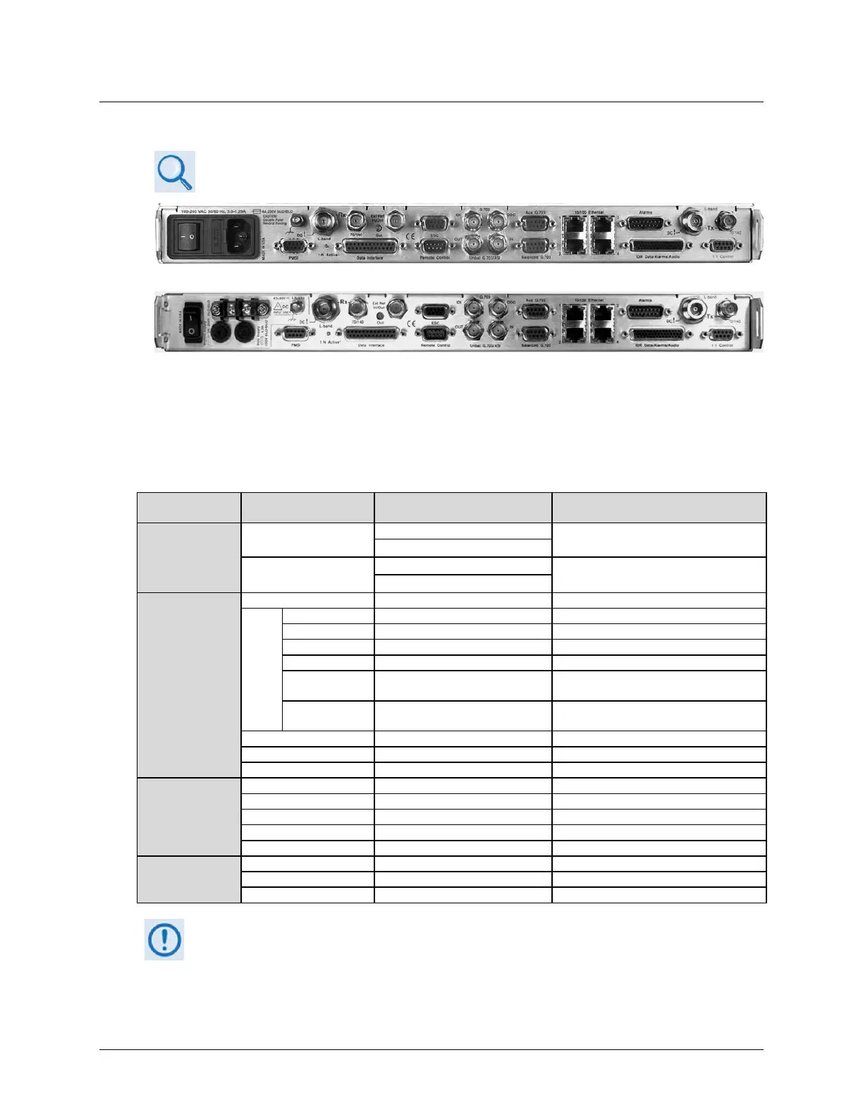
1.3.9.3 Rear Panel Features
Chapter 3. REAR PANEL CONNECTORS AND PINOUTS
(TOP) Standard AC Chassis (CEFD P/N PL-0021325)
(BOTTOM) Optional 48V DC Chassis (CEFD P/N PL-0021327)
Figure 1-4. CDM-625A Rear Panel View
Figure 1-4 shows the rear panel of the modem. External cables are attached to connectors on
the rear panel of the CDM-625A. They comprise:
Connection Group
(Chapter Sect.)
Name Connector Type Function
IF
(Sect. 3.2.1)
Rx
BNC female (70/140MHz band)
IF Input
Type ’N’ female (L-Band)
Tx
BNC female (70/140MHz band)
IF Output
Type ’N’ female (L-Band)
Terrestrial Data
(Sect. 3.2.2)
Serial synchronous data input/output
G.703
Data
G.703, D&I or D&I++; Quad E1 Ports 1 & 2
Transmit G.703 (DDI); ASI
IDI BNC female
Insert Data In / Sub-rate Auxiliary Tx G.703
In
DDO BNC female
Drop Data Output / Sub-rate Auxiliary Rx
G.703 Out
10/100 BaseT management and data
44-pin High Density Type ‘D’ female
Intelsat Open Network auxiliary signals
ESC input/output (RS232/485)
Utility
(Sect. 3.2.3
Serial Remote Interface (RS232/485)
Form C Alarms (relay closures)
Pre-Mapped Symbol Interface (CnC)
Connection to External 1:1 Controller
Ground / Power
(Sect 3.3)
#10-32 stud – See Sect. 3.3.1
The European EMC Directive 2004/108/EEC (EN 55022, EN 50024) requires using properly
shielded cables for DATA I/O. These cables must be double-shielded from end-to-end, ensuring
a continuous ground shield.