CDM-625A Advanced Satellite Modem MN-CDM625A
Rear Panel Connectors and Pinouts Revision 4
3–6
3.2.2 Terrestrial Data Connection Group
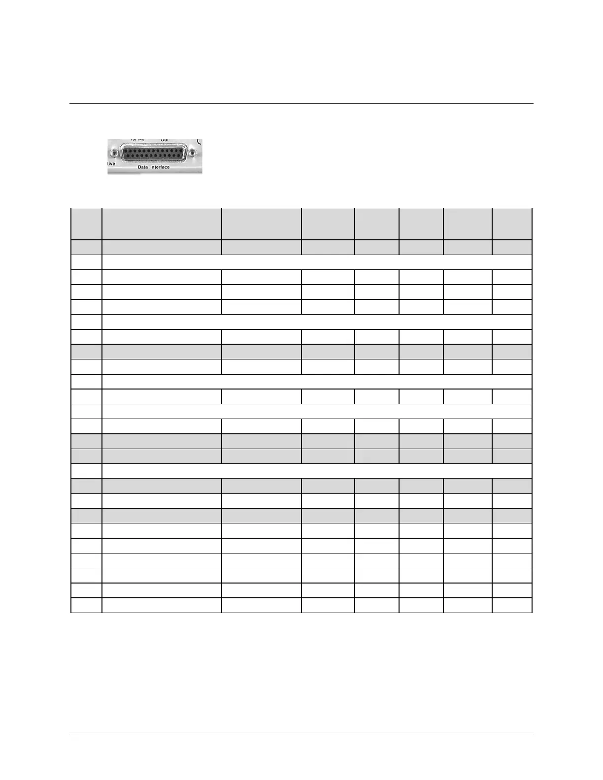
3.2.2.1 Data Interface (DB-25F)
The Data Interface connector is a 25-pin, Type ‘D’ female interface that
conducts data input and output signals to and from the modem, and
connects to customer’s terrestrial equipment, breakout panel, or
protection switch.
Table 3-1. Data Interface Connector Pinouts
(R>L)
Pin #
Generic Signal Description Direction
EIA-422
EIA 530
V.35 HSSI LVDS
Circuit
#
13 Clear to Send B * Modem to DTE CS B – – – 106
25 (NOTE 2)
12 Internal Transmit Clock B Modem to DTE ST B SCT B ST B ST B 114
24 Transmit Clock A DTE to Modem TT A SCTE A TT A TT A 113
11 Transmit Clock B DTE to Modem TT B SCTE B TT B TT B 113
23 (NOTE 2)
10 Receiver Ready B Modem to DTE RR B – CA B RR B 109
22 Data Set Ready B (NOTE 2) Modem to DTE DM B – – – –
9 Receive Clock B Modem to DTE RT B SCR B RT B RT B 115
21 (NOTE 2)
8 Receiver Ready A Modem to DTE RR A RLSD CA A RR A 109
20 (NOTE 2)
7 Signal Ground – SG SG SG SG 102
19 Request to Send B * DTE to Modem RS B - TA B – 105
6 Data Set Ready A (NOTE 2) Modem to DTE DM A DSR – – –
18 (NOTE 2)
5 Clear to Send A * Modem to DTE CS A CTS – – 106
17 Receive Clock A Modem to DTE RT A SCR A RT A RT A 115
4 Request to Send A * DTE to Modem RS A RTS TA A – 105
16 Receive Data B Modem to DTE RD B RD B RD B RD B 104
3 Receive Data A Modem to DTE RD A RD A RD A RD A 104
15 Internal Transmit Clock A Modem to DTE ST A SCT A ST A ST A 114
2 Transmit Data A DTE to Modem SD A SD A SD A SD A 103
14 Transmit Data B DTE to Modem SD B SD B SD B SD B 103
1 Shield – Shield FG Shield Shield 101
Notes:
1) When the rear-panel LED marked “1:N Active!” is OFF, all of the signals shown above are available
and functional. In addition, pins not shown are not connected, and therefore no damage will occur if
other signals are connected to the additional pins.