CDM-625A Advanced Satellite Modem MN-CDM625A
Rear Panel Connectors and Pinouts Revision 4
3–7
2) When the rear-panel LED marked “1:N Active!” is ON, the signals shown highlighted are no longer
available. Furthermore, pins 6, 18, 20, 21, 22, 23 and 25 are reserved for use by the 1:N system. DO
NOT connect signals to any of these pins in this mode. Certain pins have DC voltages present that
may damage equipment other than a Comtech EF Data redundancy switch.
3) For X.21 operation, use the EIA-422 pins, but ignore Receive Clock if the Modem is DTE, and ignore
Transmit clocks if the Modem is DCE.
4) For IDR operation using G.703, this primary interface becomes the 8 kbps EIA-422 overhead channel.
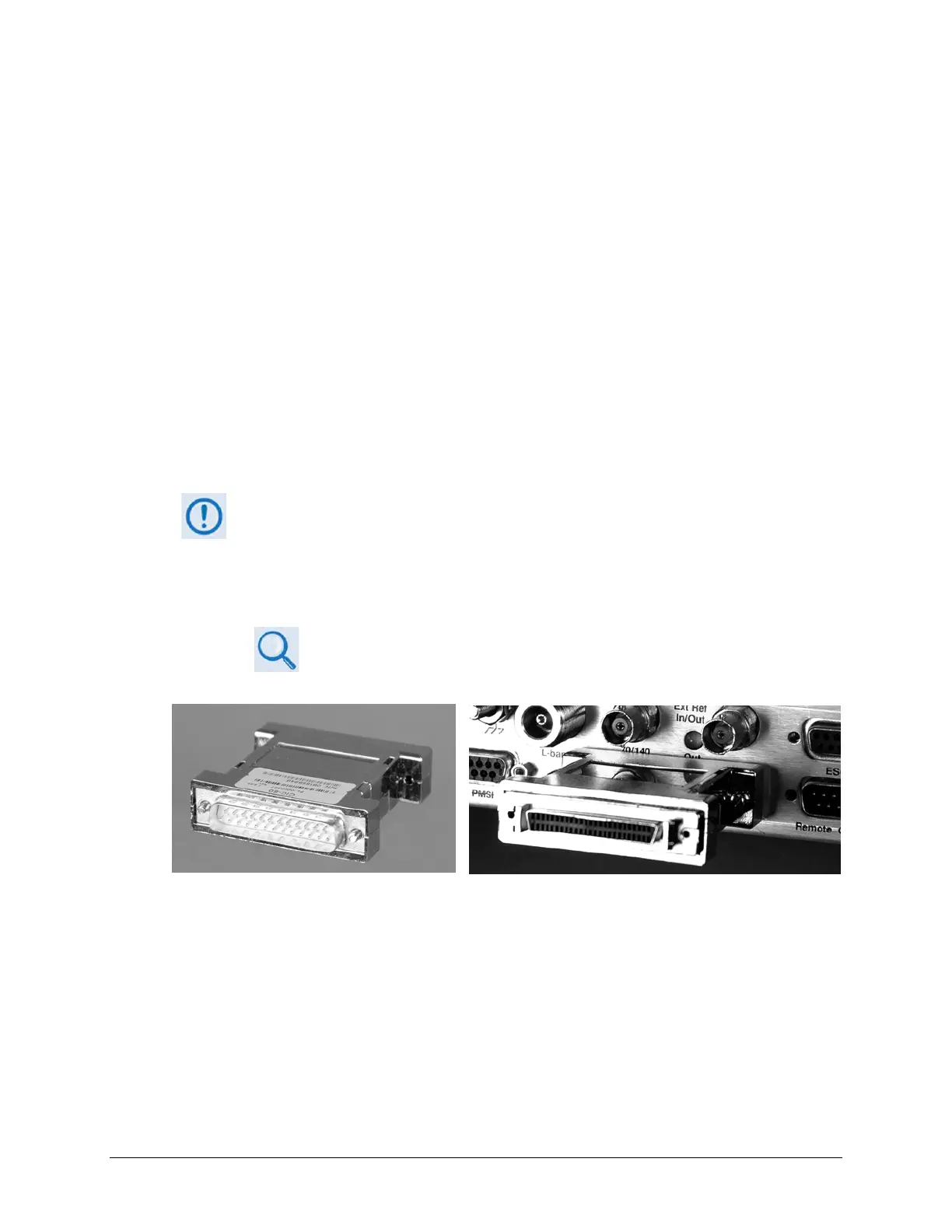
3.2.2.1.1 HSSI Operation via the CIC-60 Interface Adapter Module
For HSSI operation (Tx, Rx, or both), the optional CIC-60 Interface Adapter Module (Figure 3-4)
may be purchased from Comtech EF Data to adapt the Data Interface 25-pin Type ‘D’ female
connection to a standard 50-pin Type ‘HD’ HSSI (SCSI-II) female connection.
See Table 3-2 for the pinouts for the HSSI/EIA-613 side of the CIC-60 Adapter Module.
The modem must first be configured for the appropriate HSSI operation, via the
CDM-625A Front Panel, before using this adapter:
SELECT: Configure
Mode
(Select HSSI for both Tx Mode / Interface and Rx Mode / Interface)
Chapter 6. FRONT PANEL OPERATION
Figure 3-4. CIC-60 Interface Adapter Module (CEFD P/N PL-0000307)
CIC-60 Interface Adapter Module CIC-60 Interface Adapter Module
(Modem Interface Side) (Installed, HSSI Interface Side Shown)