CDM-625A Advanced Satellite Modem MN-CDM625A
Rear Panel Connectors and Pinouts Revision 4
3–4
3.2 CDM-625A Cabling Connections
The rear panel connectors provide all necessary external connections between the unit and
other equipment.
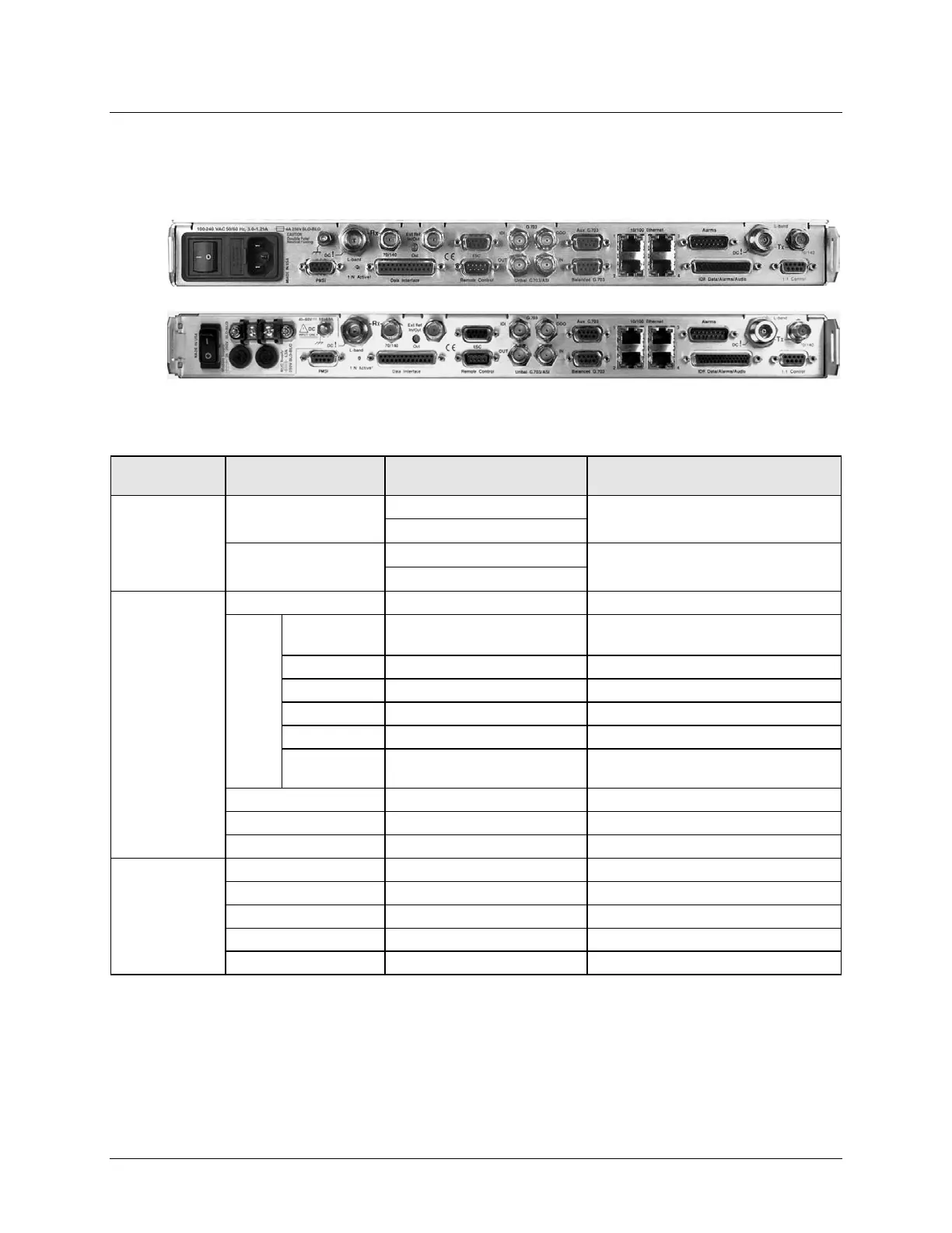
(TOP) Standard AC Chassis (CEFD P/N PL-0021325)
(BOTTOM) Optional 48V DC Chassis (CEFD P/N PL-0021327)
Connector Group
Name Connector Type Function
Sect. 3.2.1
Rx
BNC female (70/140MHz band)
IF Input
Tx
BNC female (70/140MHz band)
IF Output
Sect. 3.2.2
Serial synchronous data input/output
G.703
Data
Balanced G.703 9-pin Type ‘D’ female
G.703, D&I or D&I++;
IDI BNC female Insert Data In / Sub-rate Auxiliary Tx G.703 In
DDO BNC female
Drop Data Output / Sub-rate Auxiliary Rx G.703
10/100 Base-T management and data
44-pin High Density Type ‘D’ female
Intelsat Open Network auxiliary signals
ESC Input/output (EIA-232/485)
Utility
Sect. 3.2.3
Serial Remote Interface (EIA-232/485)
Form C Alarms (relay closures)
Pre-Mapped Symbol Interface (CnC)
Connection to External 1:1 Controller
Figure 3-3. CDM-625A Rear Panel View