CDM-625A Advanced Satellite Modem MN-CDM625A
Appendix L Revision 4
L–10
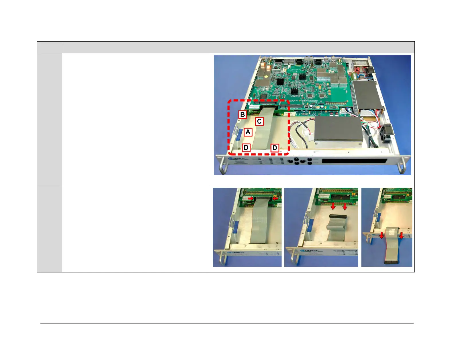
The illustration at right identifies the upgrade locations
within the chassis for:
• Installation of the fan into the chassis (A);
• Plug-in of both the fan power cable (B) and IP Packet
Processor Card (C) into the modem’s framing board;
• Assembly of the IP Packet Processor Card onto the
chassis-mounted card bosses (D).
Unplug the front panel ribbon cable from its connector on
the modem’s framing board, and then move the cable out of
the way of the upgrade location (CDM-625 chassis shown).