Parameter
structure
Keypad and
display
Parameter
x.00
Parameter
description format
Advanced parameter
descriptions
Macros
Serial comms
protocol
Electronic
nameplate
Performance
Feature look-
up table
Menu 10
Unidrive SP Advanced User Guide 175
Issue Number: 7 www.controltechniques.com
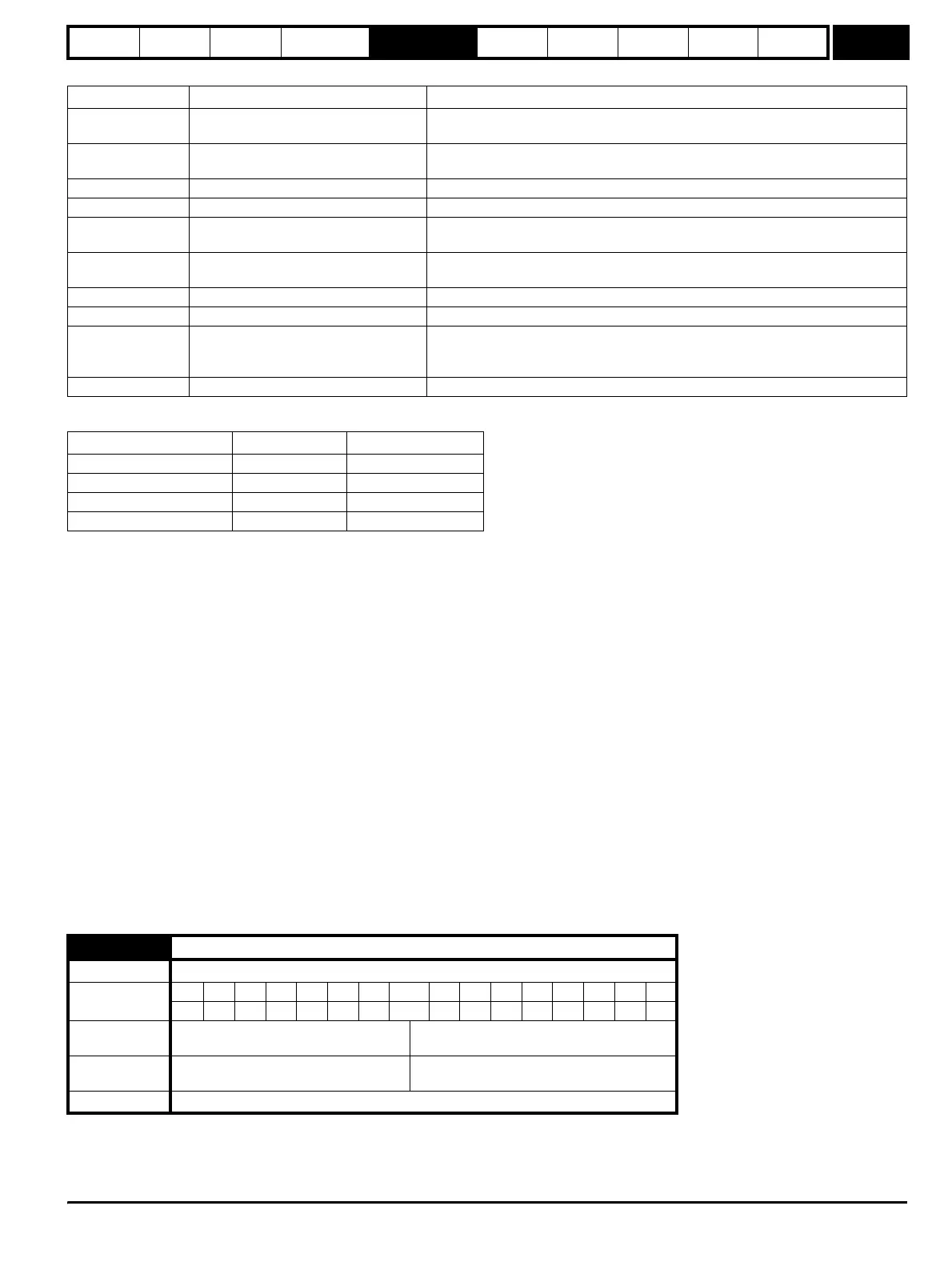
Trips can be grouped into the following categories:
*Under voltage trip and restart levels are as follows:
Trips 101 to 110 are power module trips that are initiated by the drive power electronics module, or modules for a multi-module parallel drive. The trip
identifier for each of these trips is in the form "xxxx.P". If the drive is a single module drive, and does not use the power interface intended for parallel
operation, only OIdC.P, Oht4.P and Unid.P power module trip are possible. When the trip string is displayed the trip source module number is not
displayed and the module number stored in the "module number and trip time log" is zero. If the drive is a multi-module parallel drive or a single
module drive using the power interface intended for parallel operation all the power module trips are possible, the trip source module is displayed with
the trip string and the module number is stored in the log. An ACUU.P trip is initiated if some, but not all parallel modules detect mains loss via their
input stage to ensure that the input stages of the remaining modules are not overloaded. If mains loss is detected by all modules then the normal
mains loss system based on d.c. link monitoring is used. A PH.P trip is initiated if some, but not all parallel modules detect phase loss via their input
stage. If phase loss is detected by all modules then the normal phase loss system based on monitoring the d.c. link voltage ripple is used. ACUU.P
and PH.P trips can be disabled by setting Pr 6.47 to one.
The braking IGBT continues to operate even when the drive is not enabled (except if the active supply is a low voltage supply, see Pr 6.44), but is only
disabled if any of the following trips occurs or would occur if another trip had not already become active: OI.Br, PS, It.Br or OV.
It should be noted that although the UU trip operates in a similar way to all other trips, all drive functions can still operate, but the drive cannot be
enabled. Parameter values are only loaded from EEPROM if the supply voltage is low enough for the switch mode power supply in the drive to shut
down and then it is increased to restart the drive power supplies. The differences between UU and other trips are as follows:
1. Power down save user parameters are saved when UU trip is activated except when the low voltage supply is active (Pr 6.44 = 1).
2. The UU trip is self-resetting when the DC bus voltage rises above the drive restart voltage level.
3. The drive can change between using the main high voltage supply and low voltage battery supply only when the UU trip is active.
4. When the drive is first powered up a UU trip is initiated if the supply voltage is below the restart voltage level. This does not save power down
save parameters. If another trip occurs during power-up it is the active trip in preference to the UU trip. If this trip is cleared and the supply voltage
is still below the restart voltage threshold a UU trip is then initiated.
The default value is a suitable value for standard braking resistors that can be mounted within the drive heatsink as given in the table below.
Category Trips Comments
Hardware faults HF01 to HF17
These indicate fatal problems and cannot be reset. The drive is inactive after one of
these trips and the display shows HFxx.
Self resetting trips UU
Under voltage trip cannot be reset by the user, but is automatically reset by the
drive when the supply voltage is with specification.*
Non-resettable trips HF18 to HF32, SL1.HF, SL2.HF, SL3.HF Cannot be reset.
EEF trip EEF Cannot be reset unless a code to load defaults is first entered in Pr x.00 or Pr 11.43.
Autotune initiated
trips in servo mode
tune1 - tune7, tune Can be reset after 1.0s, but only if the drive is not enabled
Normal trips with
extended reset
OI.AC, OI.Br, OIAC.P, OIBr.P, OidC.P Can be reset after 10.0s
Low priority trips Old1, cL2, cL3, SCL If Pr 10.37 is 1 or 3 the drive will stop before tripping.
Phase loss PH The drive attempts to stop before tripping.
Drive over-heat
based on thermal
model
O.ht3
The drive attempts to stop before tripping, but if it does not stop within 10s the drive
will automatically trip.
Normal trips All other trips Can be reset after 1.0s
Drive voltage rating UU trip level UU restart level
200 175 215
400 330 425
575 435 590
690 435 590
10.30 Full power braking time
Drive modes Open-loop, Closed-loop vector, Servo, Regen
Coding
Bit SP FI DE Txt VM DP ND RA NC NV PT US RW BU PS
2 111
Range
Open-loop, Closed-loop vector, Servo,
Regen
0.00 to 400.00 s
Default
Open-loop, Closed-loop vector, Servo,
Regen
See below
Update rate Background read
http://nicontrols.com