Parameter
structure
Keypad and
display
Parameter
x.00
Parameter
description format
Advanced parameter
descriptions
Macros
Serial comms
protocol
Electronic
nameplate
Performance
Feature look-
up table
Menu 11
Unidrive SP Advanced User Guide 183
Issue Number: 7 www.controltechniques.com
ANSIx3.28 protocol
Full details of the CT implementation of ANSIx3.28 are given in Chapter 7 Serial communications protocol on page 360.
Modbus RTU protocol
Full details of the CT implementation of Modbus RTU are given in Chapter 7 Serial communications protocol on page 360.
The protocol provides the following facilities:
• Drive parameter access with basic Modbus RTU
• Drive parameter access via CMP extensions
• Option module internal parameter access via CMP extensions
• Access via an option module onto a network via CMP extensions (see specific Solutions Module User Guides for details)
• Drive parameter database upload via CMP extensions
• Drive Onboard PLC program upload/download via CMP extensions
• The protocol supports access to 32 bit floating point parameters
The following product specific limitations apply:
• Maximum slave response time when accessing the drive is 100ms
• Maximum slave response time when accessing option module internal parameters or via an option module to a network may be longer than
100ms (see specific Solutions Module specifications for details)
• Maximum number of 16 bit registers that can be written to, or read from, the drive itself is limited to 16
• Maximum number of 16 bit registers that can be written to, or read from, a Solutions Module or via a Solutions Module - see Solutions Module
User Guide
• The communications buffer can hold a maximum of 128bytes
Modbus RTU protocol, but with SM-Keypad Plus only
This setting is used for disabling comms access when the SM-Keypad Plus is used as a hardware key. See section 2.6.2 'Hardware key' feature on
page 11 for more information.
Used in all comms modes to define the baud rate.
*Modbus RTU only
This parameter can be changed via the drive keypad, via a Solutions Module or via the comms interface itself. If it is changed via the comms
interface, the response to the command uses the original baud rate. The master should wait at least 20ms before sending a new message using the
new baud rate.
Parameter value String Comms mode
0 AnSI ANSIx3.28 protocol
1 rtU Modbus RTU protocol
2 Lcd Modbus RTU protocol, but only with an LCD keypad
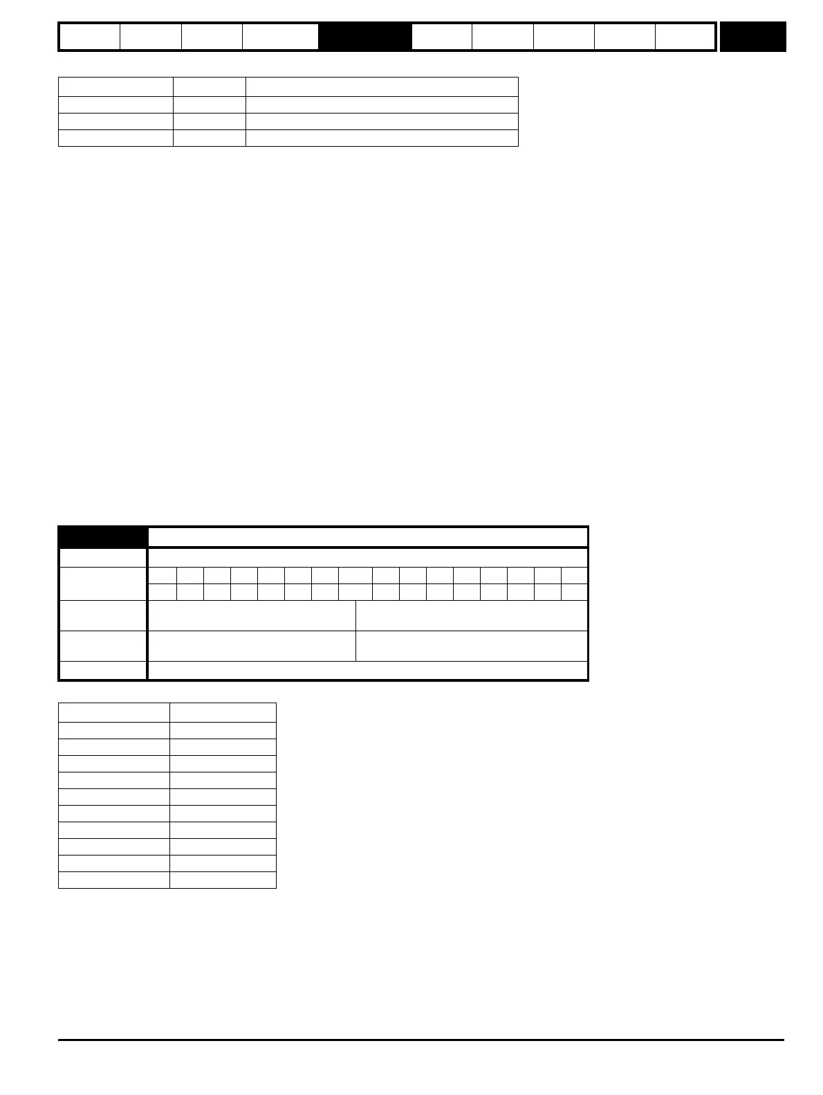
11.25 Baud rate
Drive modes Open-loop, Closed-loop vector, Servo, Regen
Coding
Bit SP FI DE Txt VM DP ND RA NC NV PT US RW BU PS
1 111
Range
Open-loop, Closed-loop vector, Servo,
Regen
0 to 9
Default
Open-loop, Closed-loop vector, Servo,
Regen
6
Update rate Background read
Parameter value String/baud rate
0300
1600
2 1200
3 2400
4 4800
5 9600
6 19200
7 38400
8* 57600
9* 115200
http://nicontrols.com