Menu 11
Parameter
structure
Keypad and
display
Parameter
x.00
Parameter
description format
Advanced parameter
descriptions
Macros
Serial comms
protocol
Electronic
nameplate
Performance
Feature look-
up table
184 Unidrive SP Advanced User Guide
www.controltechniques.com Issue Number: 7
There will always be a finite delay between the end of a message from the host (master) and the time at which the host is ready to receive the
response from the drive (slave). The drive does not respond until at least 1ms after the message has been received from the host allowing 1ms for the
host to change from transmit to receive mode. This delay can be extended using Pr 11.26 if required for both ANSI and Modbus RTU protocols.
Note that the drive holds its own transmit buffers active for up to 1ms after it has transmitted data before switching to the receive mode, and so the
host should not send any data during this time.
Modbus RTU uses a silent period detection system to detect the end of a message. This silent period is either the length of time for 3.5 characters at
the present baud rate or the length of time set in Pr 11.26, whichever is the longest.
If this parameter is zero the drive is a standard Unidrive SP product. If this parameter is non-zero then the product is a derivative product. Derivatives
can have different defaults from the standard product and restrictions on the values allowed for some parameters.
The drive software version consists of three numbers xx.yy.zz. Pr 11.29 displays xx.yy and zz is displayed in Pr 11.34. Where xx specifies a change
that affects hardware compatibility, yy specifies a change that affects product documentation, and zz specifies a change that does not affect the
product documentation.
If any number other than 0 is programmed into this parameter user security is applied so that no parameters except Pr 11.44 can be adjusted with the
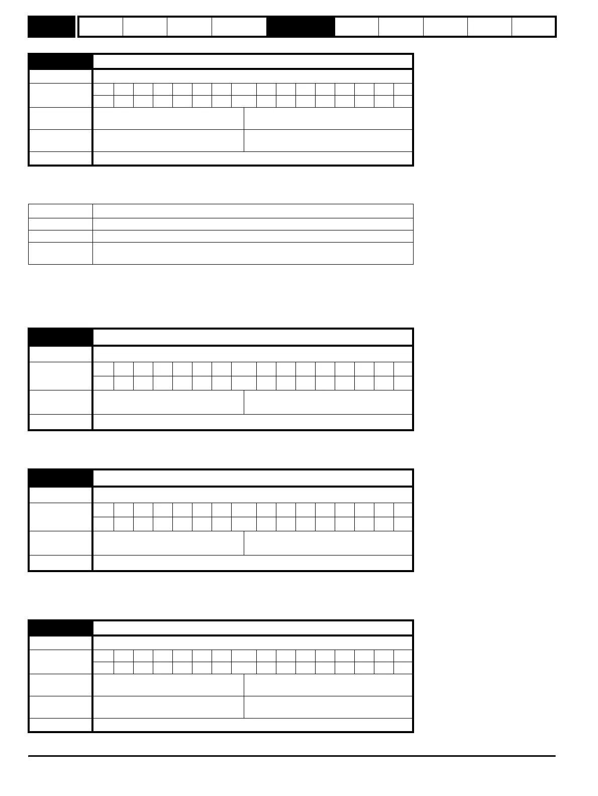
11.26 Minimum comms transmit delay
Drive modes Open-loop, Closed-loop vector, Servo, Regen
Coding
Bit SP FI DE Txt VM DP ND RA NC NV PT US RW BU PS
111
Range
Open-loop, Closed-loop vector, Servo,
Regen
0 to 250 ms
Default
Open-loop, Closed-loop vector, Servo,
Regen
2
Update rate Background read
Pr 11.26 Action
0 The transmit buffers are turned on and data transmission begins immediately.
1 The transmit buffers are turned on and data transmission begins after 1ms.
2 or more
The transmit buffers are turned on after an additional delay of (Pr 11.26 – 1)ms and data
transmission begins after a further 1ms delay.
11.28 Drive derivative
Drive modes Open-loop, Closed-loop vector, Servo, Regen
Coding
Bit SP FI DE Txt VM DP ND RA NC NV PT US RW BU PS
111 1
Range
Open-loop, Closed-loop vector, Servo,
Regen
0 to 16
Update rate Write at power-up
11.29 Software version
Drive modes Open-loop, Closed-loop vector, Servo, Regen
Coding
Bit SP FI DE Txt VM DP ND RA NC NV PT US RW BU PS
21 1 1 1
Range
Open-loop, Closed-loop vector, Servo,
Regen
1.00 to 99.99
Update rate Write at power-up
11.30 User security code
Drive modes Open-loop, Closed-loop vector, Servo, Regen
Coding
Bit SP FI DE Txt VM DP ND RA NC NV PT US RW BU PS
1 1 1 111
Range
Open-loop, Closed-loop vector, Servo,
Regen
0 to 999
Default
Open-loop, Closed-loop vector, Servo,
Regen
0
Update rate Background read
http://nicontrols.com