Parameter
structure
Keypad and
display
Parameter
x.00
Parameter
description format
Advanced parameter
descriptions
Macros
Serial comms
protocol
Electronic
nameplate
Performance
Feature look-
up table
Menu 12
Unidrive SP Advanced User Guide 199
Issue Number: 7 www.controltechniques.com
5.13.1 Brake control function
The brake control function can be used to control an electro-mechanical brake via the drive digital I/O. A brake control function is provided for open-
loop operation of induction motors (Open-loop mode) and an alternative brake control function is provided for closed-loop operation of induction
motors or servo motors (Closed-loop vector and Servo modes). The parameters that are common to both brake control functions (Pr 12.40 and Pr
12.41) are described below. The other parameters used by each of the brake control functions are then described in the section for the appropriate
function.
This parameter should be used as a source for a digital output to control an electro-mechanical brake. This parameter is one to release the brake and
zero to apply the brake. Digital I/O can be automatically configured to use this parameter as a source (see Pr 12.41).
0 = dis
The brake controller is disabled and no other drive parameters are affected by the brake controller. When this parameter is changed from a non-zero
value to zero the following parameters are set to zero: Pr 2.03 (all modes), Pr 6.08 (Closed-loop vector and Servo modes), Pr 13.04 and Pr 13.10
(Closed-loop vector and Servo modes if Pr 12.49 = 1).
1 = rel
The brake controller is enabled with I/O set up to control the brake via the relay output T41/42. Drive healthy is re-routed to digital I/O 2 (T25).
2 = d IO
The brake controller is enabled with I/O set up to control the brake via digital I/O 2 (T25).
3 = User
The brake controller is enabled, but no parameters are set to select the brake output.
The following tables show the automatic parameter changes that occur to set up digital I/O2 (T25) and the relay output (T41/42) after drive reset when
Pr 12.41 has been changed. The changes are done in two stages: the first stage restores the I/O used as defined by the initial setting of Pr 12.41 and
the second stage sets up the I/O as defined by the new setting of Pr 12.41.
Stage 1: Restore I/O
Stage 2: Set-up I/O
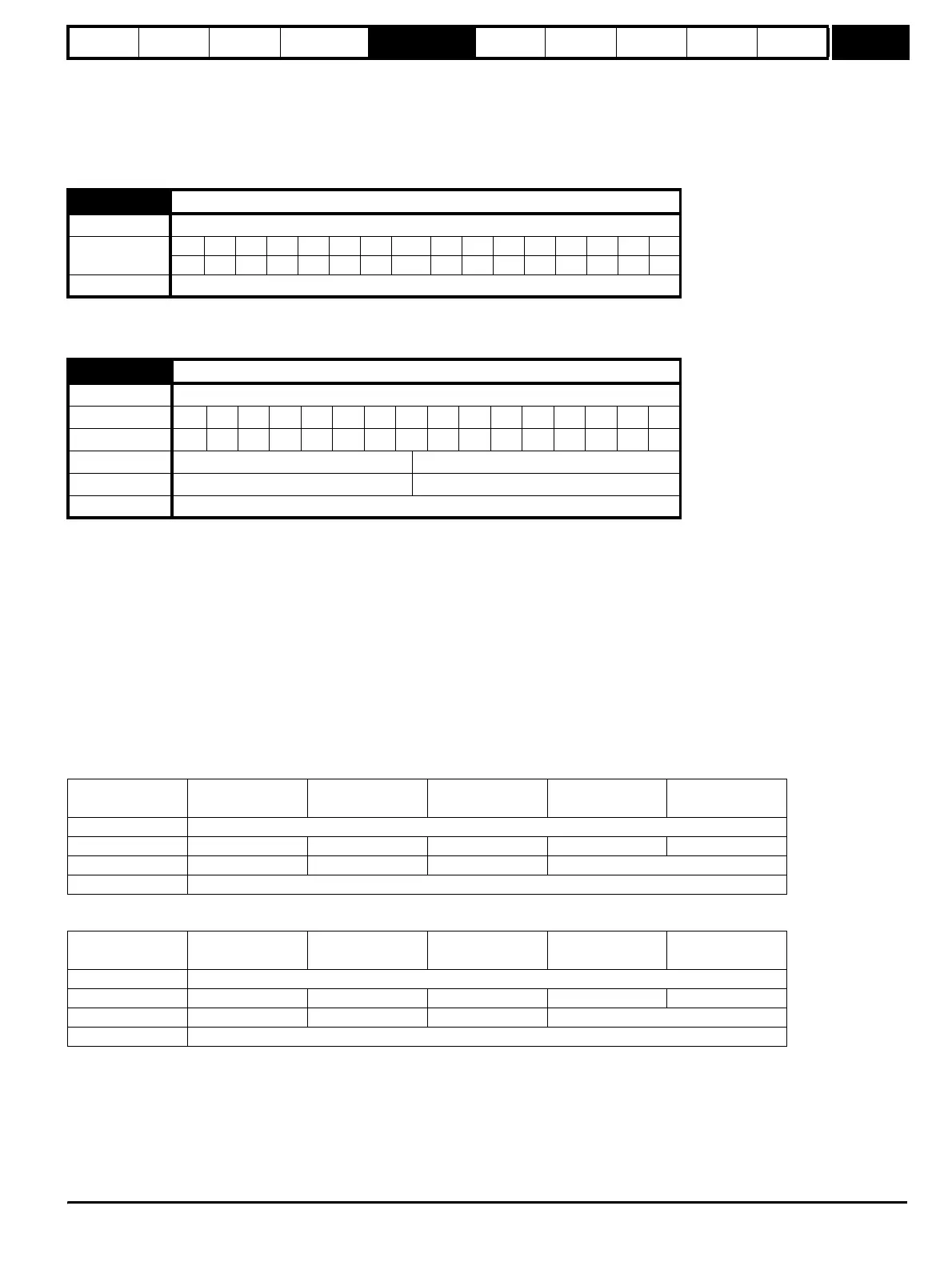
12.40 Brake release
Drive modes Open-loop, Closed-loop vector, Servo
Coding
Bit SP FI DE Txt VM DP ND RA NC NV PT US RW BU PS
1111
Update rate Background read
12.41
Brake controller enable
Drive modes Open-loop, Closed-loop vector, Servo
Coding Bit SP FI DE Txt VM DP ND RA NC NV PT US RW BU PS
1 111
Range Open-loop, Closed-loop vector, Servo 0 to 3
Default Open-loop, Closed-loop vector, Servo 0
Update rate Read on drive reset
Initial setting in
Pr 12.41
Pr 8.12 (Invert)
Pr 8.22 (Source /
destination)
Pr 8.32 (Input/
output)
Pr 8.17 (Invert) Pr 8.27 (Source)
0 No action
10Pr 10.33 00Pr 10.01
20Pr 10.33 0 No action
3 No action
Initial setting in
Pr 12.41
Pr 8.12 (Invert)
Pr 8.22 (Source /
destination)
Pr 8.32 (Input/
output)
Pr 8.17 (Invert) Pr 8.27 (Source)
0 No action
10Pr 10.01 10Pr 12.40
20Pr 12.40 1 No action
3 No action
http://nicontrols.com