Menus 15 to 17
SM-I/O Plus
Parameter
structure
Keypad and
display
Parameter
x.00
Parameter
description format
Advanced parameter
descriptions
Macros
Serial comms
protocol
Electronic
nameplate
Performance
Feature look-
up table
270 Unidrive SP Advanced User Guide
www.controltechniques.com Issue Number: 7
The error status is provided so that only one Solutions Module error trip is required for each Solutions Module slot. If an error occurs the reason for
the error is written to this parameter and the drive may produce a SLotx.Er trip, where x is the slot number. A value of zero indicates that the module
has not detected an error, a non-zero value indicates that an error has been detected. (See descriptions for each category for the meaning of the
values in this parameter.) When the drive is reset this parameter is cleared for all Solutions Modules.
All modules include a temperature monitoring circuit. If the PCB temperature exceeds 90°C the drive fan is forced to operate at full speed (for a
minimum of 10s). If the temperature falls below 90°C the fan can operate normally again. If the PCB temperature exceeds 100°C the drive is tripped
and the error status is set to 74.
Most Solutions Modules include a processor with software. The software version is displayed in these parameters in the form Pr x.02 = xx.yy and Pr
x.50 = zz. Where xx specifies a change that affects hardware compatibility, yy specifies a change that affects product documentation, and zz specifies
a change that does not affect the product documentation. When a module is fitted that does not contain software both these parameters appear as
zero.
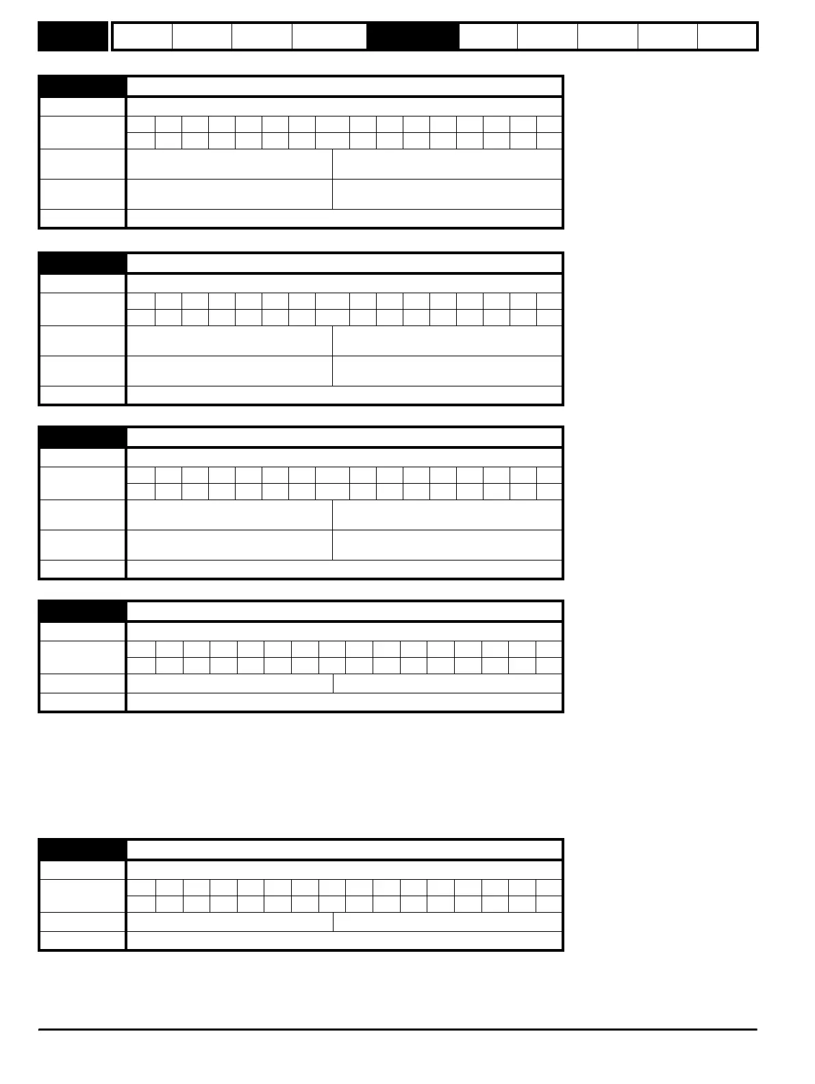
x.47 Analog input 2 destination
Drive modes Open-loop, Closed-loop vector, Servo, Regen
Coding
Bit SP FI DE Txt VM DP ND RA NC NV PT US RW BU PS
1 2 1111
Range
Open-loop, Closed-loop vector, Servo,
Regen
Pr 0.00 to Pr 21.51
Default
Open-loop, Closed-loop vector, Servo,
Regen
Pr 0.00
Update rate Read on reset
x.48 Analog output 1 source
Drive modes Open-loop, Closed-loop vector, Servo, Regen
Coding
Bit SP FI DE Txt VM DP ND RA NC NV PT US RW BU PS
2 1111
Range
Open-loop, Closed-loop vector, Servo,
Regen
Pr 0.00 to Pr 21.51
Default
Open-loop, Closed-loop vector, Servo,
Regen
Pr 0.00
Update rate Read on reset
x.49 Analog output 1 scaling
Drive modes Open-loop, Closed-loop vector, Servo, Regen
Coding
Bit SP FI DE Txt VM DP ND RA NC NV PT US RW BU PS
3 111
Range
Open-loop, Closed-loop vector, Servo,
Regen
0.000 to 4.000
Default
Open-loop, Closed-loop vector, Servo,
Regen
1.000
Update rate Background read
x.50 Solutions Module error status
Drive modes Open-loop, Closed-loop vector, Servo, Regen
Coding
Bit SP FI DE Txt VM DP ND RA NC NV PT US RW BU PS
111 1
Range Open-loop, Closed-loop, Servo, Regen 0 to 255
Update rate Background write
x.51 Option software sub-version
Drive modes Open-loop, Closed-loop vector, Servo, Regen
Coding
Bit SP FI DE Txt VM DP ND RA NC NV PT US RW BU PS
111 1
Range Open-loop, Closed-loop, Servo, Regen 0 to 99
Update rate Write on power-up
http://nicontrols.com