Parameter
structure
Keypad and
display
Parameter
x.00
Parameter
description format
Advanced parameter
descriptions
Macros
Serial comms
protocol
Electronic
nameplate
Performance
Feature look-
up table
342 Unidrive SP Advanced User Guide
www.controltechniques.com Issue Number: 7
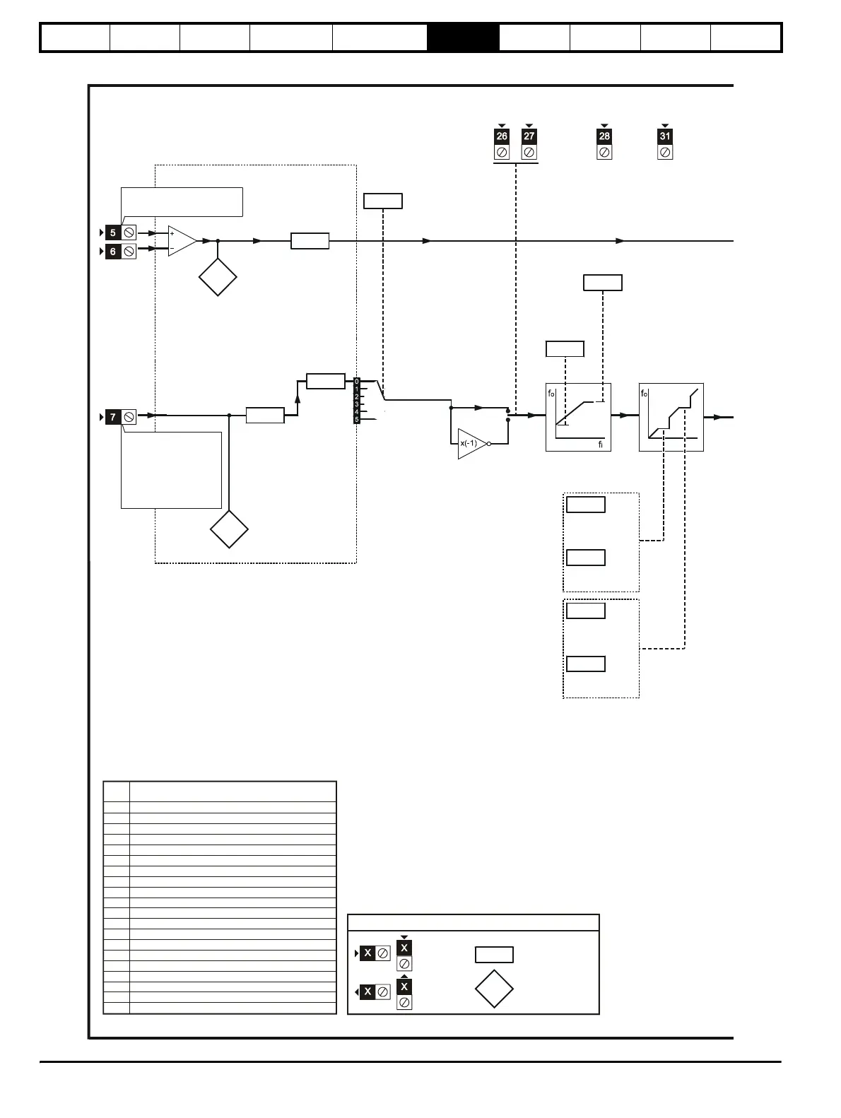
Figure 6-4 Macro 4 Torque control logic diagram
Reference selection
Analog torque
reference
RUN
FORWARD
RUN
REVERSE
RESET
0.05
Reference
selector
Maximum
frequency/speed
clamp
0.01
0.02
0.20
0.21
0.22
0.23
Skip frequency/
speed 1
Skip freq./speed
band 1
Skip frequency/
speed 2
Skip freq./speed
band 2
Skip frequencies/
speeds
DRIVE
ENABLE
Analog
input 1
0.25
0.26
Analog
input 2
mode
selector
Freq./speed control:
Frequency /speed
reference
Torque control:
OL> (Not used)
CL> Speed over-ride
Analog
input 1
scaling
0.29
0.30
0.27
Analog
input 2
Analog
input 2
scaling
Minimum
frequency/speed
clamp
Pr Function
0.11 Pre-ramp reference
0.12 Post-ramp reference
0.13 Motor active-current
0 14 Jog reference (not used)
0.15 Braking mode
0.16 Stop mode
0.17 Status relay
0.18 S-ramp
0.19 S-ramp da/dt
0.20 Skip frequency/speed 1
0.21 Skip freq./speed band 1
0.22 Skip frequency/speed 2
0.23 Skip freq./speed band 2
0.24 (Not used)
0.25
0.26
0.27
0.28 Over-speed threshold
0.29
0.30
selector
selector
invert
enable
Analog input 1(torque reference)
Analog input 2 mode
Analog input 2 (maximum speed override level)
Analog input 1 scaling
Analog input 2 scaling
selector
0.XX
0.XX
Key
Read-write (RW)
parameter
Read-only (RO)
parameter
Input
terminals
Output
terminals
Menu 0 changes from default configuration
http://nicontrols.com