IMS.OM.002949.DRM Page 306 of 310 Version 1.4
Doremi Labs
25 Appendix H: Installing the Ferrite Cores
Six ferrite cores are included for installation on to the Ethernet and GPI/GPO cables that
connect to the IMS1000. A ferrite core can help reduce unwanted high-frequency interference
received by these cables.
Install one ferrite core 2 inch/5.1mm from each end of the Ethernet cables, near the
RJ45 plugs that will be connected to the IMS1000 Eth0 & Eth1 connectors.
Install one ferrite core 2 inch/5.1mm on each Ethernet cable near the RJ45 plug that will
be connected to the IMS1000 GPI/GPO connectors.
25.1 Mounting the Ferrite Core Clamp
Open the ferrite core clamp and attach it 2 inch/5.1mm to the end of the cable that is
closest to the connector that is to be attached to the IMS1000.
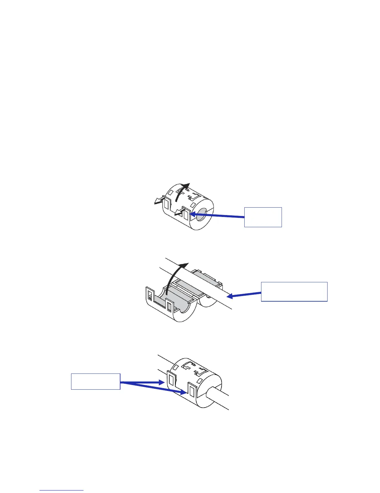
o If nessecary, push the catch to open the ferrite core clamp (Figure 341).
Figure 341: Clamp Catch
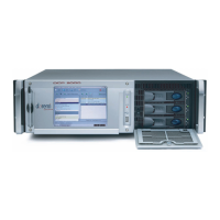
Close the ferrite core clamp tightly around the cable (Figure 342).
Figure 342: Attaching the Clamp
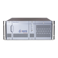
Push the tabs until they close securely with a snapping sound (Figure 343).
Figure 343: Clamp Tabs
The procedure is now complete.
Place near end of
cable connectors