IMS.OM.002949.DRM Page 58 of 310 Version 1.4
Doremi Labs
5.4 GPI/GPO Cables Installation
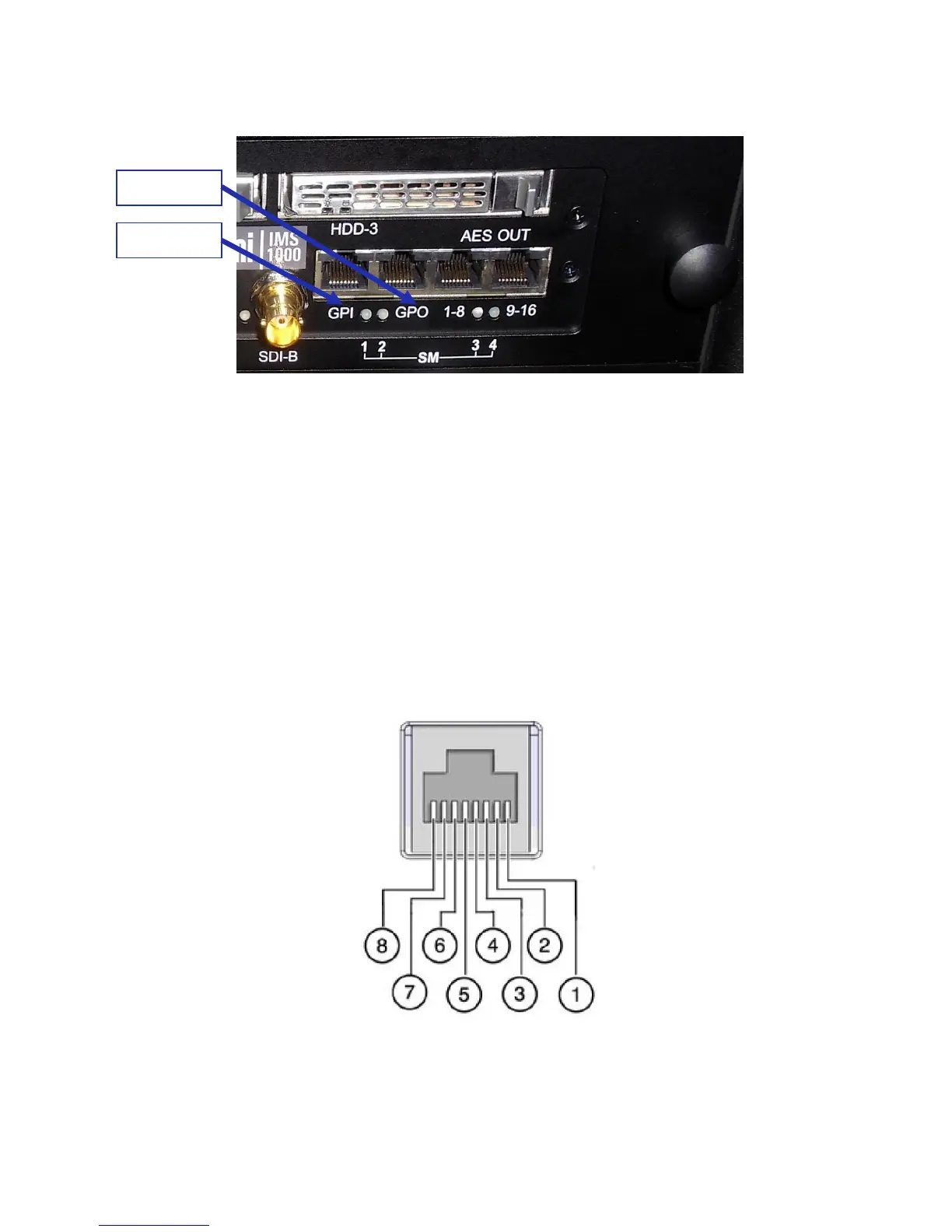
Figure 51: GPI/GPO Connectors
● Plug one shielded CAT5 or CAT6 cable end into the connector labeled GPI on the
IMS1000 board (Figure 51). Install a ferrite core clamp near the connector closest to the
IMS1000. Refer to Section 2525 for more information on ferrite core clamp installation.
● Plug the other end of the shielded CAT5 or CAT6 cable into whichever automation
controller is available or required.
● Take another shielded CAT5 or CAT6 cable and plug the end into the IMS1000
connector labeled GPO (Figure 51). Install a ferrite core clamp near the connector
closest to the IMS1000. Refer to Section 25 for more information on ferrite core clamp
installation.
● Plug the other end of the shielded CAT5 or CAT6 cable into whichever automation
controller is available or required.
5.4.1 GPI/GPO Pin-Out Information
Figure 52: RJ45 Socket Pin-Out