IMS.OM.002949.DRM Page 41 of 310 Version 1.4
Doremi Labs
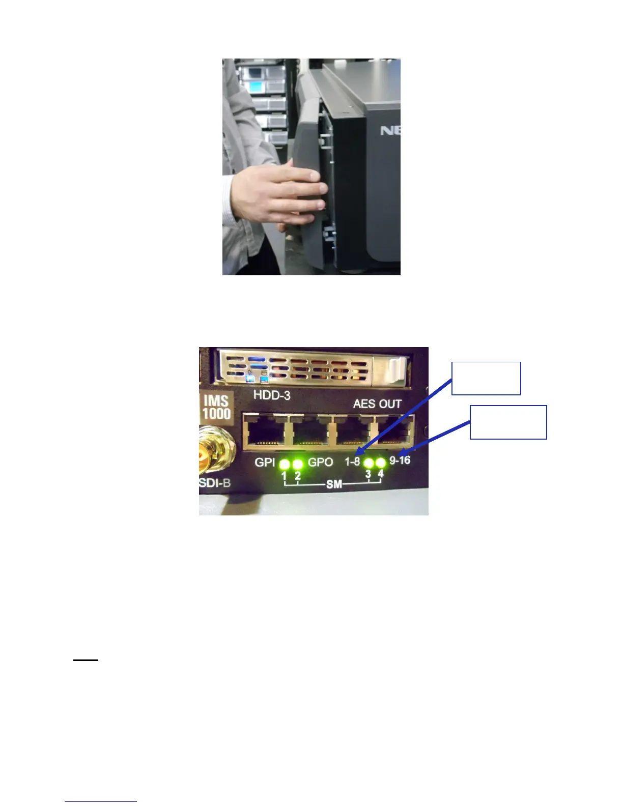
Figure 20: Reattaching the Filter Cover
4.4 Audio Cables Installation
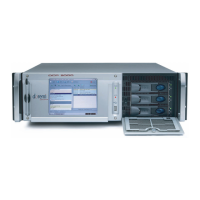
Figure 21: Audio Connectors
● Plug one shielded CAT5 or CAT6 cable end into the connector labeled AES-OUT 1-8 on
the IMS1000 board (Figure 21).
● Plug the other end of the shielded CAT5 or CAT6 cable into the audio processor.
● Take another shielded CAT5 or CAT6 cable and plug the end into the connector labeled
AES-OUT 9-16 (Figure 21).
● Plug the other end of the shielded CAT5 or CAT6 cable into the audio processor.
Note: If the audio processor does not have RJ-45 connectors but has a single DB25 connector,
then you will need to use the RJ-45 to DB25 converter that is provided with the IMS1000 (Figure
22).