D 30 29
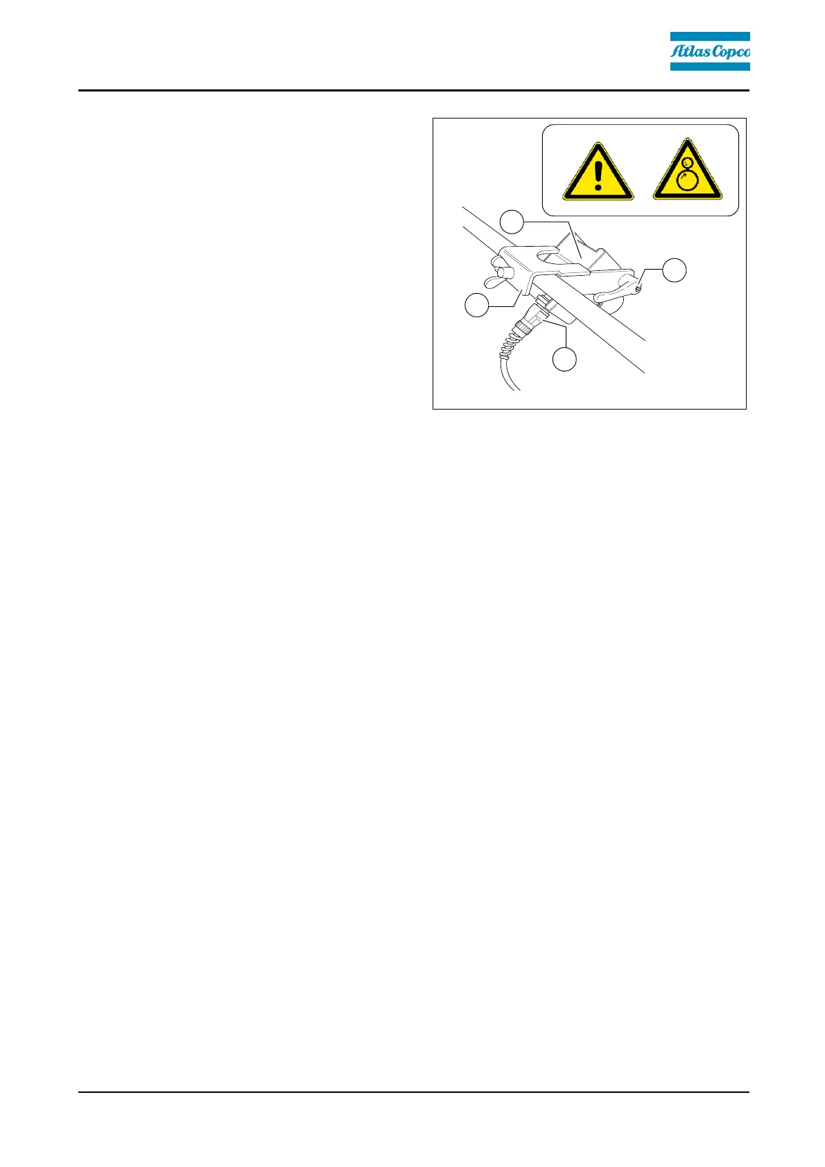
Ultrasonic auger limit switches (left
and right) - PLC version
A
The limit switches control the material
flow at the relevant half of the auger
without contact.
The ultrasonic sensor (1) is secured to
the side shield via a bracket (2).
- To adjust, release the clamping lever /
stop screw (3) and adjust the sensor's
angle.
- After adjusting, retighten all mounting
parts properly.
A
The connection cables (4) are connected to the relevant sockets on the remote con-
trol bracket.
A
The sensors should be adjusted so that 2/3 of the augers are covered with the paving
material.
A
The paving material must be conveyed over the full working width.
A
We recommend adjusting the limit switch positions during material distribution.
A
In vehicles with a PLC control system, the deactivation point is set on the remote con-
trol.