100
Program description - Base setup models | Helicopter models
Caution:
Never start the range test on the
transmitter during normal operation
of the model.
DSC output
If necessary, use the selection keys of the left
or right touch pad to switch to the “DSC Output” line
then, with a brief tap on the centre SET key of the
right touch pad, activate the value window:
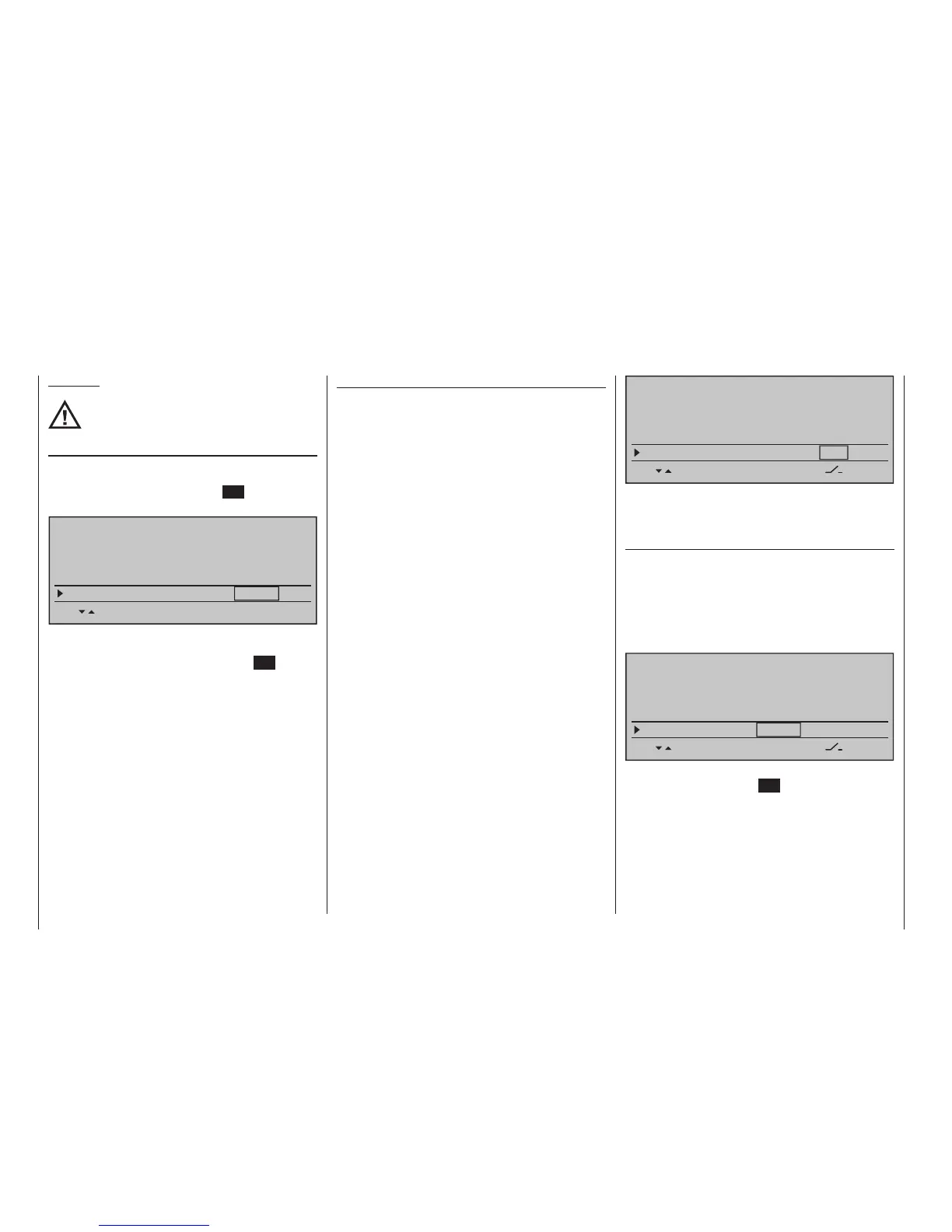
SET SET SEL SET
Rcv Ch Map R16 R08
n/a
n/a
RF transmit on
RF range test 99s
DSC Output PPM10
BASIC SETTING,MODEL
Now you can use the right selection keys to choose
between four types of modulation “PPM10”, “PPM16”,
“PPM18” and “PPM24”. Touch the centre SET key of
the right touch pad again to complete the entry.
This choice primarily influences the maximum num-
ber of control channels which can be attached to the
DSC (direct servo control) socket, and thus also avail-
able to a flight simulator or teacher/pupil system. By
selecting “PPM10” this will be control channels 1 … 5,
for “PPM16” channels 1 … 8, for “PPM18” channels 1
… 9 and for “PPM24” channels 1 … 12.
Autorotation
Autorotation is that state of descending flight in which
the pitch of main rotor blades are set such that the
rotor's speed matches the natural forces of air flowing
through, like a windmill. This built-up energy can be
used for "recovery" lift to brake a descent by appropri-
ate blade pitch adjustment.
Autorotation is a means by which real and model heli-
copters are able to land safely in emergency situations,
e. g. in the event of a motor failure. However, the pre-
requisite for this is a well-trained pilot familiar with the
helicopter's characteristics. Quick reaction and good
perceptiveness are necessary because the rotor's iner-
tia can only be used once to generate recovery lift.
When this technique is evaluated during competi-
tions, the motor must be switched off for autorotation.
On the other hand, for training mode it is advanta-
geous to keep the motor at idle for autorotation.
The Autorotation switch causes a switchover to the
autorotation flight phase in which control of "throttle"
and "pitch" are separate and all mixers which have
an effect on the throttle servo are switched off. Cor-
responding parameter settings are made in the »Heli-
copter mixer« (see text beginning page 190); refer
also to the "Principle of the Auto. C1 Pos." topic which
follows.
The "Autorotation" name is permanently assigned to
this phase and it is included in the base screen and
the screeens of all flight phase dependent menus.
This name can NOT be changed. It is only possible to
assign a switch to this option at the right of this display,
as described on page 60. If a switch is assigned,
it will have absolute priority over all other ight-
phase switches.
BASIC SETTING,MODEL
SET SET
RF transmit on
RF range test 99s
DSC Output PPM10
–––
Autorotation
More about flight-phase programming can be found
in the text beginning on page 190 in the»Helicopter
mixer« section.
Autorotation C1 position
The autorotation flight-phase can alternatively be acti-
vated by a threshold point for the C1 throttle/pitch stick.
To do this, use the selection keys of the left or right
touch pad to move into the "Autorot. C1-Pos." line.
As soon as this display line has been selected, its
value field, located above the column label STO will
be framed.
BASIC SETTING,MODEL
STO SET
RF range test 99s
DSC Output PPM10
–––
Autorotation
Autorot. C1-Pos. 0%
–––
Move the C1 stick into the desired threshold switchover
position then tap the centre SET key of the right touch
pad. The current value will be displayed, e. g.: