122
Program description - Control adjust | Helicopter models
Control adjust
Basic procedure for transmitter control and switch assignment
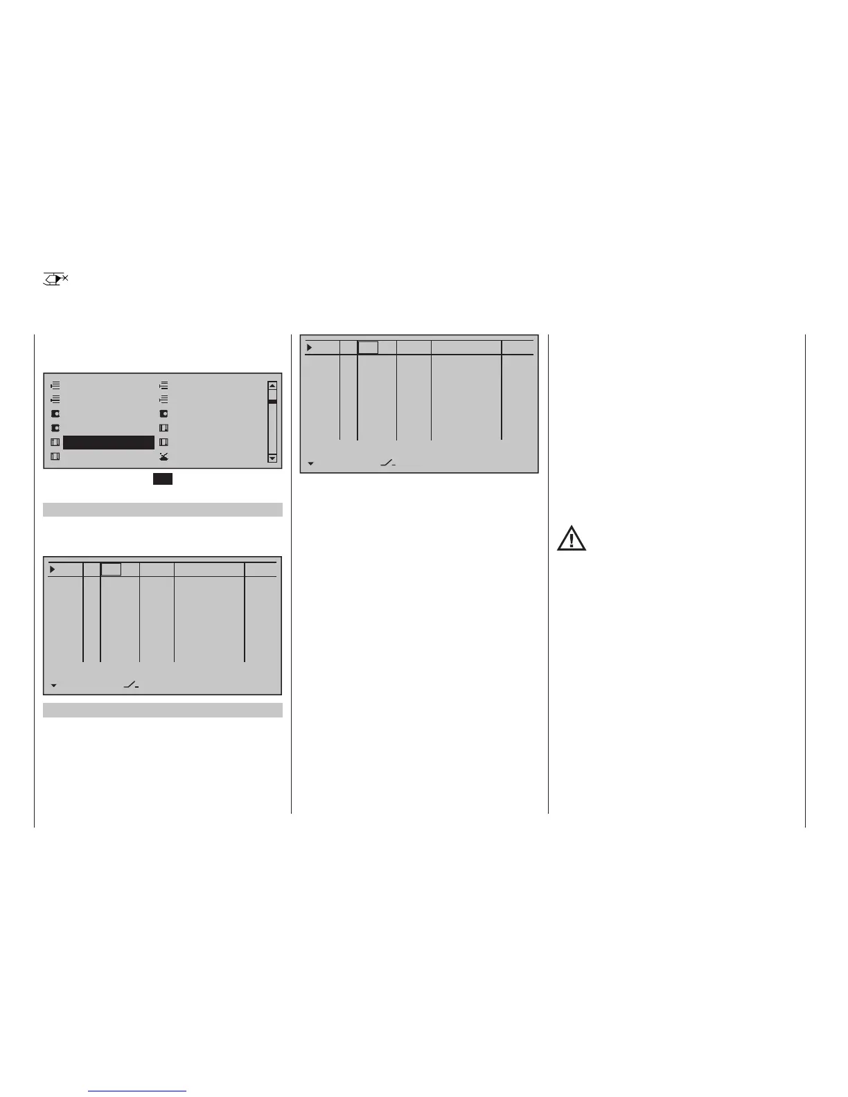
Use the selection keys on the left or right touch pad
to scroll to the »Control adjust« option in the multi-
function menu:
Model select
Servo adjustment
Stick mode
Control adjust
Dual Rate / Expo
Channel 1 curve
Switch display
Copy / Erase
Suppress codes
Suppress models
Base setup model
Helicopter type
Tap briefly on the centre SET key of the right touch
pad to open this menu option:
Firmware version V1102 and lower
By default, the input “GL16” preset with the right side
of the transmitter mounted proportional rotary slider
SD1:
0%
+100%I5
Thr6
Gyr7
I8
TYP
SEL
+100%
0.0 0.0
– travel + –time+
0%
+100%
+100%
0.0 0.0
0%
+100%
+100%
0.0 0.0
0%
+100%
+100%
0.0 0.0
GL
GL
GL
GL
fr ---
fr
fr
fr
---
---
---
Offset
I15 GL
0%
+100%
+100%
0.0 0.0
fr ---
…
…
…
…
…
…
…
…
…
Tl16 GL
0%
+100%
+100%
0.0 0.0
LV1 ---
Firmware version V1103 and higher
From the firmware version of the “GL12” input after
initializing a new model memory with the model type
“Helicopter” is enabled by default “free”:
0%
+100%I5
Thr6
Gyr7
I8
TYP
SEL
+100%
0.0 0.0
– travel + –time+
0%
+100%
+100%
0.0 0.0
0%
+100%
+100%
0.0 0.0
0%
+100%
+100%
0.0 0.0
GL
GL
GL
GL
fr ---
fr
fr
fr
---
---
---
Offset
I15 GL
0%
+100%
+100%
0.0 0.0
fr ---
…
…
…
…
…
…
…
…
…
Tl16 GL
0%
+100%
+100%
0.0 0.0
fr ---
In addition to the two sticks for control functions 1 to 4
and their trim wheels, the mc-32 HoTT transmitter
also has other controls as standard equipment:
• two 3-way switches
• two 2-way switches
• two unlockable 2-way switches
• two self-restoring 2-way switches
• three proportional sliders on the middle console,
designated Sl 1 … 3 in the menu
• two side-mounted "rotary sliders", designated Lv1
and 2 in the menu
• two depressible "rotary controls", designated Tv2
and 4 in the menu
• three roller-shaped rotary controls, designated as
Tv1, Tv3 and Tv5 in the menu
In contrast to the two sticks which, even for a newly
initialized "Helicopter" model type will automatically
use the servos attached to receiver outputs 1 … 4
and 6, the aforementioned "other" operating ele-
ments – except for the standard assignment of servo 6
to the right-side proportional slider, designated in this
menu as Lv1 (throttle limiter) – are initially inactive.
One of the effects of this is that (as already men-
tioned on page 68) with a factory-fresh system – as
with a newly initialized model memory for a "Helicop-
ter" model type following its "binding" to the intended
receiver – only those servos connected to receiver
outputs 1 … 4 and – depending on the position of
the throttle limiter – servo 6 can be moved by the two
sticks. Any servos connected to plug-in locations
5 and 7 through 15, on the other hand, will simply
remain at their centre positions.
While this may appear a bit awkward at first glance
… this is the only way to ensure a completely free
selection from among "additional" operating elements
while, at the same time, not requiring the "deactiva-
tion" of unused operating elements. This is because:
The only way to ensure an unused operat-
ing element can have no effect on the
model, even if operated by accident, is to
make it inactive, i. e. not assigned to any function.
All of the aforementioned operating elements can be
freely assigned in this »Control adjust« menu to any
function input, see page 58, just to accommodate
personal requirements.
Equally, this also means that each of these operating
elements can also be assigned to to multiple func-
tions at the same time, as needed. For example: the
exact same toggle switch assigned to an input in this
menu can, at the same time, also have an assign-
ment in the »Timers (general)« menu, see page 58,
as an "On/Off" switch, etc.
Furthermore, all inputs can be selectively set to glob-
al or ight-phase specic operation if they have been
defined for flight-phases in the »Phase settings«
menu, page 154, and »Phase assignment« menu,
page 164.