259
Program description - Telemetry
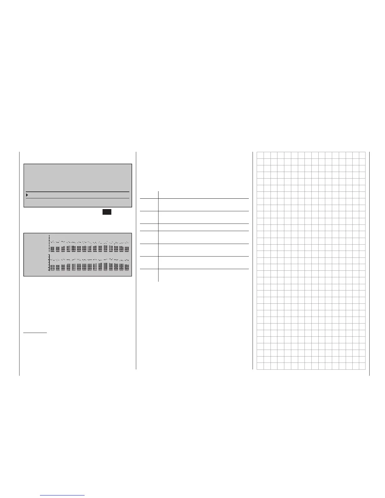
After selection of the desired menu line with the
selection keys of the left or right touch pad …
TELEMETRY
SETTING & DATAVIEW
SENSOR SELECT
RF STATUS VIEW
VOICE TRIGGER
TELEMETRY RCV
BIND. 1
VOLT.E
… and a subsequent tap on the centre SET key of the
right touch pad will open the selected sub-menu. This
provides a visualization of the quality of the connec-
tion of transmitter and receiver:
E100%
SL 22
P 10
RL 41
4.8RS
S 95%
4.8RM
0 1 2 3 4 5 6 7 8 9 A B C D E
Top row: Reception power of the channels 1 …
75 of the 2.4 GHz band in dBm com-
ing from the receiver to the transmit-
ter.
Bottom row: Reception power of the channels
1 … 75 of the 2.4 GHz band in dBm
coming from the transmitter to the
receiver.
Comments:
• Since reception power is measured and presented
in dBm, reception power is increasingly worse
the higher the bar is and vice versa; refer also to
"Reception power (S-dBm)" on page 246 about
this.
RF STATUS VIEW
• The points above the bars mark the poorest
reception since switching on the transmitter or
the last reset of the display with a simultaneous
tap on the or keys of the right touch pad
(CLEAR).
Additional figures are shown to the left of the graphic
representation of the reception power. These mean:
Value Explanation
R Signal quality in % of the signal received
from the receiver
S Signal quality in % of the signal received
by the receiver
T Reception power in dBm
E Number of lost data packages of the re-
ceiver
R Reception power in dBM of the signal
received by the receiver
VC Current operating voltage of the receiver
in volts
VM Lowest receiver operating voltage since
last startup, in volts