213
Program description - Free mixers
left touch pad. This menu gives you the
opportunity to check the effects of all of
your settings on a single screen.
Mixer ratios and mixer neutral point
Now that we have explained the wide-ranging nature
of the mixer functions, the following section describes
how to program linear and non-linear mixer curves.
For each of the 12 available mixers, the mixer curves
are programmed on a second page of the screen
display. Use the selection keys on the left or right
touch pad to select the desired mixer line. If neces-
sary, use the touch pad's selection keys to move to
the right column (“=
”
) then briefly tap the centre SET
key of the right touch pad to access the graph page.
LinearMIX 1 … 8: Setting linear mixer values
As a practical example, we will now define a linear
mixer curve to resolve the following problem:
For a motorized aircraft model, the two servos con-
nected to receiver outputs 6 and 7 – defined on
the "Aile/flaps" line of the »Model type« menu as
“… 2FL" – are to be used for actuating landing flaps.
That is; when a transmitter control is moved, they
must deflect downwards only. This requires a simulta-
neous elevator trim, however.
First allocate, for example, input 6 to the leftmost
slider control Sl1 located in the middle of the console
by making settings in the »Control adjust« menu.
A transmitter control on input 6, – as shown in the
above table – will control the two servos connected
to receiver outputs 6 and 7 by default as flaps. Leave
the default value of "GL" in the "Type" column alone,
however, to configure this setting globally for all flight
phases – as is the case for the free mixer.
»Control adjust« menu
0%
+100%I5
I6
I7
I8
Ty p
SEL
+100%
0.0 0.0
– travel + –time+
0%
+100%
+100%
0.0 0.0
0%
+100%
+100%
0.0 0.0
0%
+100%
+100%
0.0 0.0
GL
GL
GL
Sl1 ---
fr
fr
fr
---
---
---
offset
GL
Normal
Note:
Note that if two ap servos have been
selected, any transmitter control assigned to
input 7 will be decoupled in the software in
order to avoid errors in operating the aps. However,
in the interests of safety, you should make a habit of
leaving all inputs not currently required to "free", or of
resetting these back to "free"!
Start by moving this transmitter control to its forward
limit and adjust the landing flaps so that they are
retracted or closed in this position. If you now move
the dial to the rear, the flaps should move downward;
if not the direction of servo rotation must be adapted.
We now turn our attention to the first mixer shown in
the screen image on page 210 ("6 EL"), to which
switch 4 was assigned:
EL
LinearMIX 1
type
6
from – Begr. +
EL
C1
8
3
EL
S
??
??
––––
LinearMIX 2
LinearMIX 3
LinearMIX 4
LinearMIX 5
to
Adjust
4
C4
2
off
off
off
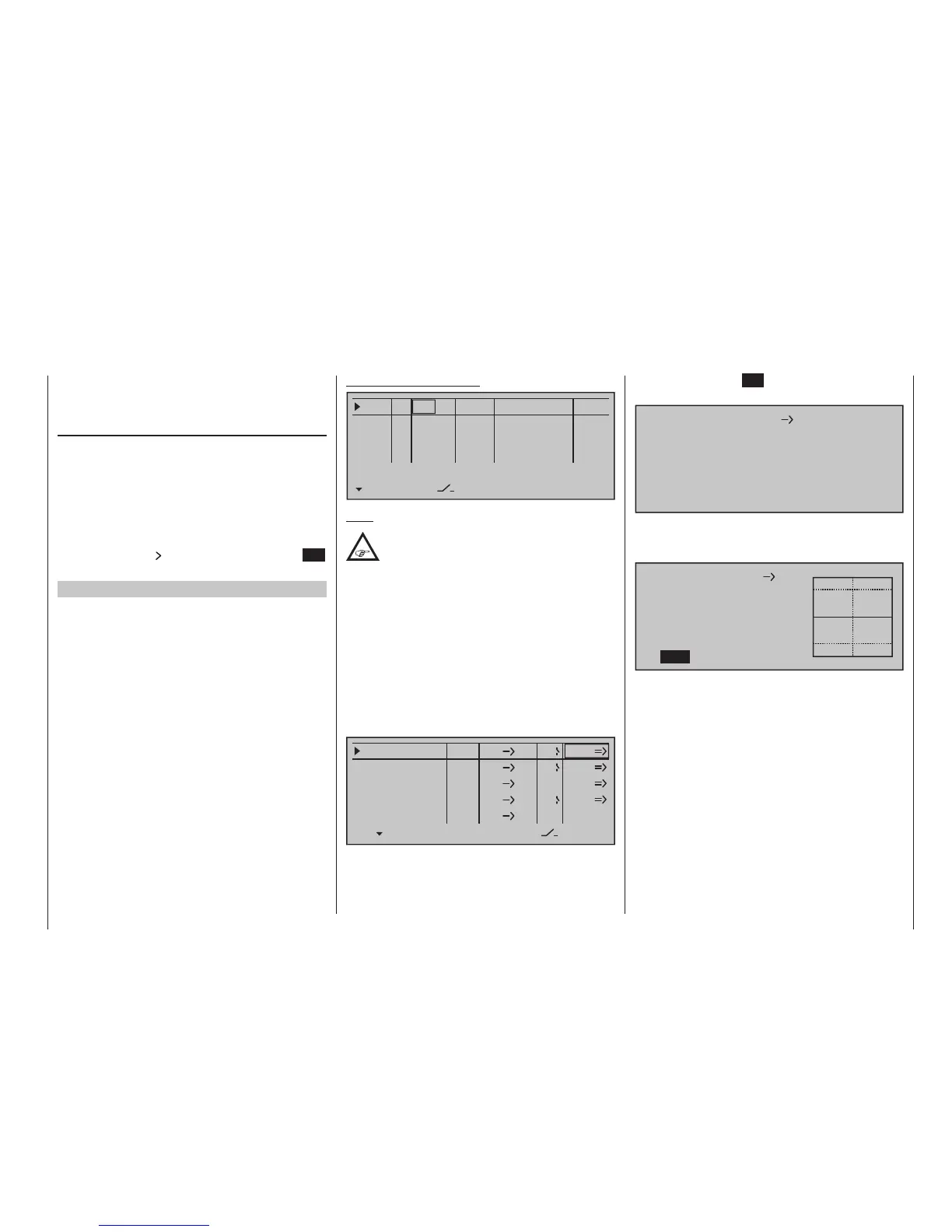
Briefly tap the centre SET key of the right touch pad
to open the second screen page:
Linear MIX 1
EL
6
off
If this screen appears, the mixer has not yet been
activated in combination with the assigned toggle
switch – "4", in this example. If so, operate the switch:
6
Mix input
0%
Offset
0%
EL
Linear MIX 1
0%
SYM ASY
SET
STO
The continuous vertical line represents the current
position of the transmitter control linked to input 6.
(However, it is not visible in the above graphic be-
cause it is at the left edge since slider control Sl1, in
this example assigned to input 6 (see previous page),
is at its forward limit.) The dotted vertical line in the
middle of the diagram indicates the position of the
mixer neutral point – see under "Offset", below. The
solid horizontal line shows the mixer ratio, which cur-
rently has the value zero over the entire stick travel;
accordingly, the elevator will not yet follow the move-
ment of the flaps.
First, the …