255
Program description - Telemetry
The servo connections of the receiver are
controlled in parallel in blocks of four. This means
channels 1 through 4, 5 through 8 and 9 through
12 each receive the control signals simultaneously.
This is recommended for digital servos when
multiple servos are used for one function (e. g.
aileron), so that the servos can run absolutely
synchronized.
When only using digital servos, we recommend
setting the "PERIOD" line of the »RX SERVO« to
10 ms in order to be able to utilize the fast reaction
of digital servos. With the use of analog servos or
in mixer mode, 20 ms must be selected!
With this setting, pay particular
attention to the sufcient dimensioning
of the receiver current supply. Since up
to four servos can always operate simultaneously,
the requirement is higher.
• SUMO (sum signal OUT)
A HoTT receiver configured as SUMO permanently
generates a so-called sum signal from the control
signals of all of its control channels and provides
this by default to the accompanying GR-32 DUAL
receiver on servo connection 8, labelled with “- + S”.
On receivers whose right of “SUMO”, an additional
two-digit number in the display appears …
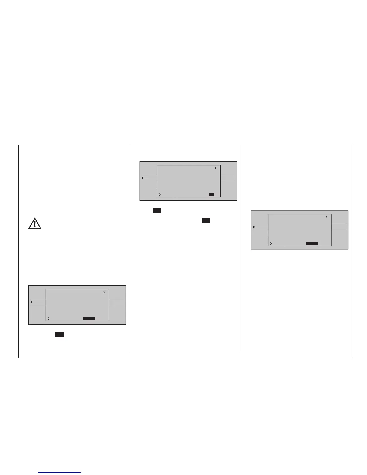
TELEMETRY
SETTING & DATAVIEW
SENSOR SELECT
RF STATUS VIEW
VOICE TRIGGER
TELEMETRI RCV
BIND. 1
VOLT.E
RX SERVO TEST
ALL–MIN : 1000µsec
ALL–MAX : 2000µsec
ALARM VOLT : 3.8V
ALARM TEMP–:–10°C
ALARM TEMP+: 70°C
TEST : START
CH OUT TYPE:SUMO 12
… after confirmation of "SUMO" with a brief tap
on the centre SET key of the right touch pad,
the active field changes to the right for channel
selection.
With this selection you specify the highest of the
transmitter channels contained in the SUMO
signal:
TELEMETRY
SETTING & DATAVIEW
SENSOR SELECT
RF STATUS VIEW
VOICE TRIGGER
TELEMETRI RCV
BIND. 1
VOLT.E
RX SERVO TEST
ALL–MIN : 1000µsec
ALL–MAX : 2000µsec
ALARM VOLT : 3.8V
ALARM TEMP–:–10°C
ALARM TEMP+: 70°C
TEST : START
CH OUT TYPE:SUMO 12
Either confirm the default with another tap on the
centre SET key of the right touch pad or use the
selection keys to pick another channel between
04 and 16 and confirm that with SET.
Receiver outputs will be controlled successively in a
20 ms cycle (30 ms with the GR-32 DUAL receiver,
No. 33516), even if 10 ms is set in the "PERIOD"
line of the »RX SERVO« screen.
Primarily intended for the "Satellite mode" of
two HoTT receivers, as described below, the
sum signal generated by the SUMO-designated
receiver can also be used, for example, to
control of Flybar systems (provided they have an
appropriate input) or to control flight simulators via
an adapter cable, No. 33310
In …
Satellite mode
… two HoTT receivers are connected to one
another through a three-wire connecting cable
(No. 33700.1 (300 mm) or 33700.2 (100 mm)) at
receiver-type-specific servo connections. Type GR-
16 (No. 33508) and GR-24 (No. 33512) receivers,
for example, are to be connected with one another
at servo output 8.
Type GR-32 DUAL No. 33516 receiver, features
a proper sumdsignal output labelled with “+ S” on
the left lower side. More detailed information can
be found on the Internet at www.graupner.de.
This connection transmits all channels of the
HoTT receiver configured as SUMO as well as
those of the receivers designated as satellites
continuously to the second HoTT receiver, which
is to be programmed as …
• SUMI (sum signal IN)
… the designation for the main receiver. Therefore,
the signal always goes toward SUMI:
TELEMETRY
SETTING & DATAVIEW
SENSOR SELECT
RF STATUS VIEW
VOICE TRIGGER
TELEMETRI RCV
BIND. 1
VOLT.E
RX SERVO TEST
ALL–MIN : 1000µsec
ALL–MAX : 2000µsec
ALARM VOLT : 3.8V
ALARM TEMP–:–10°C
ALARM TEMP+: 70°C
TEST : START
CH OUT TYPE:SUMI
The receiver defined as SUMI, however, only uses
the sum signal coming from SUMO in the event of
a failure of receipt if at least one channel in SUMI
is programmed to fail-safe.
If the receiver programmed as the SUMO satellite
receiver has a reception outage, the servos
connected to this receiver assume the fail-safe
positions which were programmed into the satellite
receiver, completely independent of the main
receiver.
On the other hand, if two receivers have a
reception outage simultaneously, the fail-safe
settings in the current receiver software at the time
this manual went to print (in principle, the SUMO's
fail-safe settings) become effective.