22
General operating notices
Holder bracket for transmitter straps
A stable transmitter hanger for fastening neck straps
is standard equipment on the
mc-32 HoTT trans-
mitter.
To unfold the holder brackets, fi rst press both brack-
ets inward a bit near where they are lettered then turn
them upward by 90 °. The brackets will automatically
lock into position.
If you have a neck strap fastened to the holder brack-
et with key-rings, fi rst press lightly on the right holder
bracket to release its latch so it can be folded down
then do the same with the left holder bracket. After-
ward, press both brackets SIMULTANEOUSLY into
the recess.
The following straps are available as accessories:
No. Description
71.26 Transmitter straps, Graupner HoTT
72.40 Transmitter straps, deluxe
Installation of switches, switch modules and knob
modules
There are a total of 20 holes in the transmitter's hous-
ing available for mounting accessory modules.
ATTENTION:
To be safe, always disconnect the transmitter
battery before installation to avoid short cir-
cuit conditions. Be sure to pay attention that
soldered points on the transmitter board do not come
into contact with metal objects!
Unoccupied holes in the transmitter's housing are
closed with blind plugs. These can easily be pulled
out from the outside with one's fi ngernails.
Insert the accessory switch, etc. through a hole in the
housing from the inside.
Accessory switches, potentiometers, etc. are fastened
into place by screwing a nut onto the threaded shaft
protruding though the housing and tightening it with
a suitable wrench. If the control has a knob, it can be
reattached after the nut is tightened down. Trim nut
wrench (No. 5733) is well suited for tightening down
these nuts.
Trim nut wrench (No. 5733) is well suited for
tightening down switch element trim nuts.
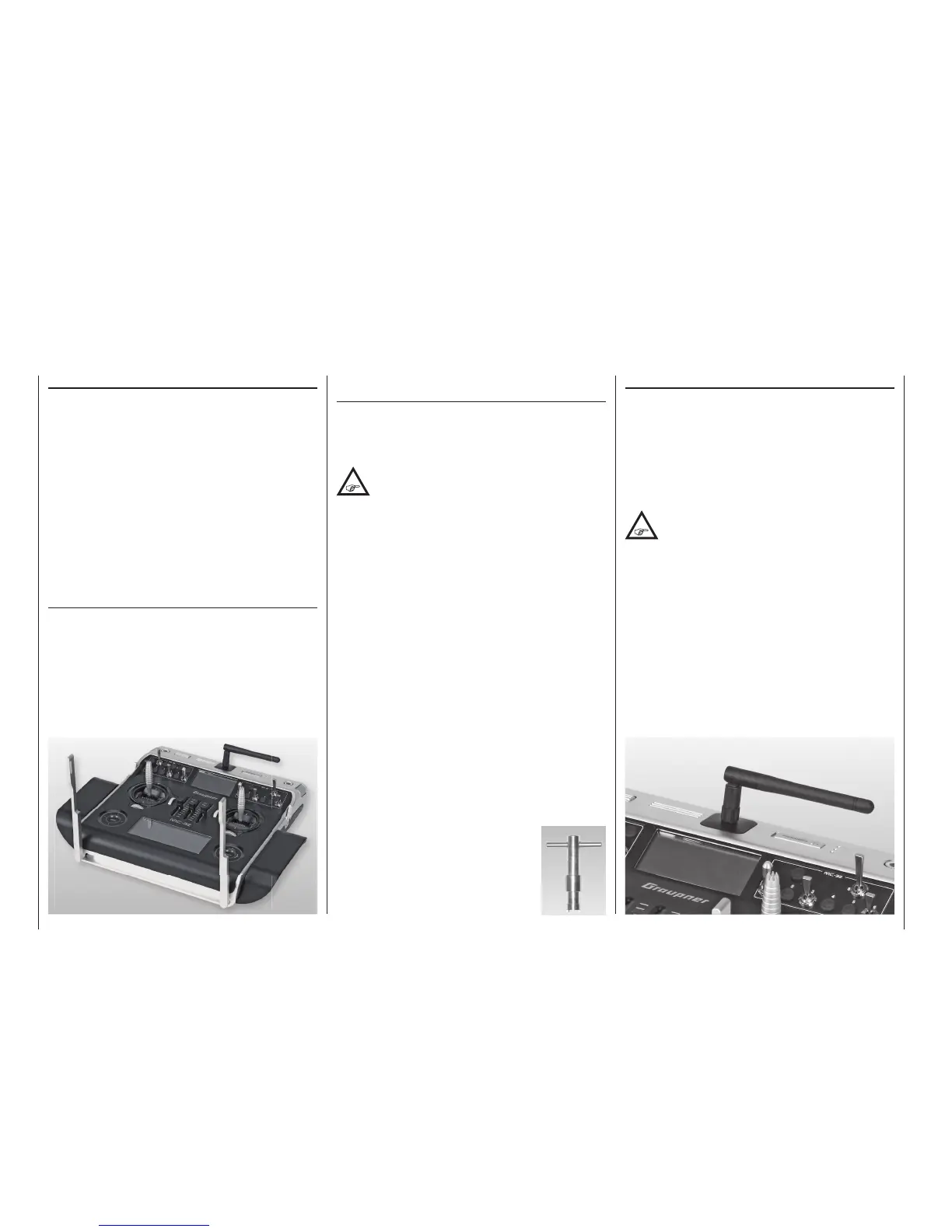
Aligning the antenna
The removable, articulated antenna is to be screwed
into the ball-joint connector then aligned by hand.
The antenna exhibits very limited fi eld strength
straight out from its end, pointing it directly toward the
model is wrong.
ATTENTION:
When screwing in the antenna, pay attention
that the centre pin in the antenna socket does
not get bent or pressed back in the socket.