143
Program description - Channel 1 curve | Helicopter models
Channel 1 curve
Control characteristics for throttle/collective pitch stick
Using the selection keys of the left or right touch pad,
scroll to the »Channel 1 curve« menu option in the
Multi-function menu:
Model select
Servo adjustment
Stick mode
Control adjust
Dual Rate / Expo
Channel 1 curve
Switch display
Copy / Erase
Suppress codes
Suppress models
Base setup model
Helicopter type
Open this menu option with a tap on the centre SET
key of the right touch pad.
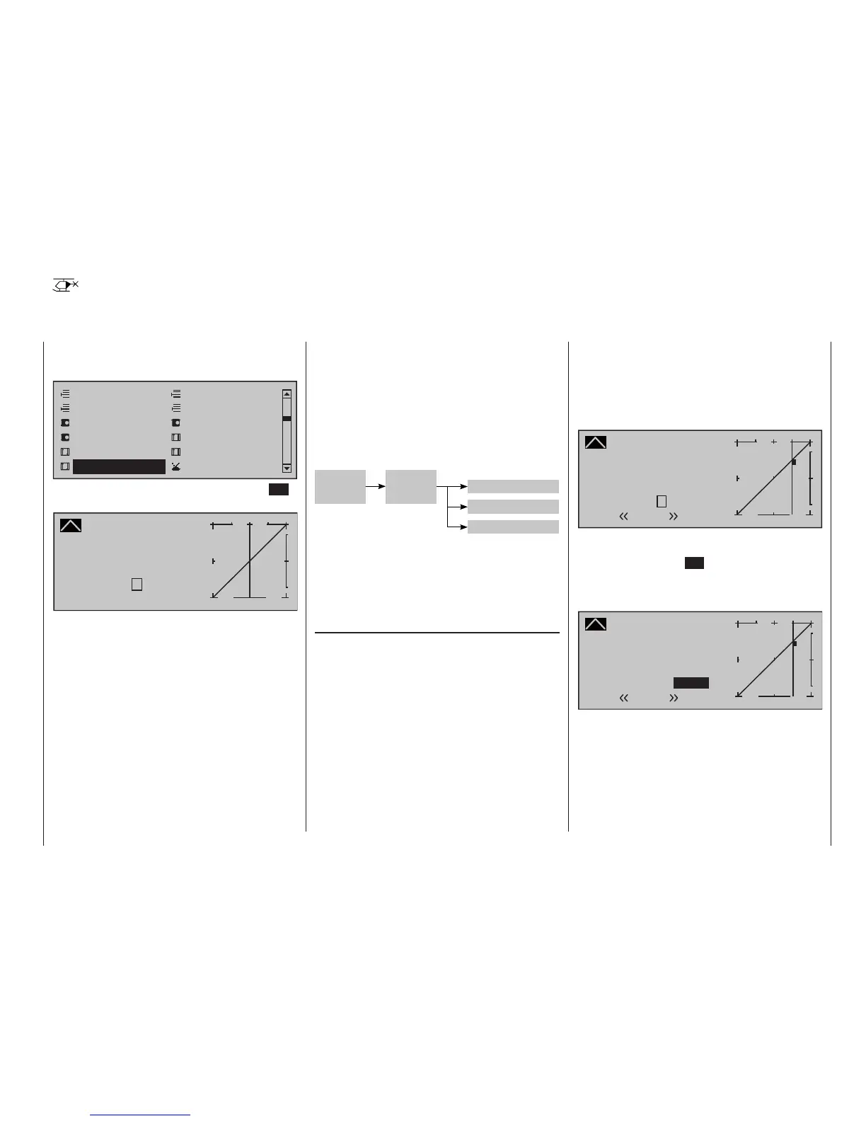
Channel 1 CURVE
Curve
off Point
Output
Input 0%
0%
?
+
–
100
O U T P U T
0%
Since the carburettor response or the effect of collec-
tive pitch is often non-linear, you can make compen-
satory adjustments to these in this menu.
The menu therefore enables modification of the con-
trol characteristics of the motor/collective pitch stick,
regardless of whether this control function affects the
servo connected to control channel 1 directly or af-
fects multiple servos via various mixers.
If flight phases have been specified in the »Phase
settings« and »Phase assignment« menus (see
pages 158 and 160) this option can be adapted on
a flight-phase basis. The given flight phase name,
e. g. «normal», will be shown at the bottom left of
the screen.
The control curve can be defined by up to 8 points
(termed "reference points" below) placed anywhere
along the path of stick travel. While the on-screen
graph considerably simplifies the process of setting
and adjusting the reference points, we recommend
that you set fewer reference points to begin with.
Please note that the curve characteristic you set
here acts as the input signal for specific mixers in the
»Helicopter mixer« menu, page 190.
»Heli-Mixer«
C1
C-1-
curve
Pitch
Thr
Pitch-
stick
In the basic software set-up, 2 reference
points – namely the end-points at the bottom end of
stick travel ("L", low = -100 % travel) and the top end
of stick travel ("H", high = +100 % travel) – define a
linear characteristic curve.
First, switch to your chosen flight phase, if necessary.
Setting reference points
By moving the transmitter control (motor/collective
pitch stick), you can reposition the vertical line in the
graph between the two end-points "L" and "H". The
current stick position is also displayed in numerical
form on the "Input" line (-100 % to +100 %). The point
at which this line crosses the curve is termed the
"Output", and can be varied at the reference points
within the range -125 % to +125 %. The control sig-
nal altered in this way will then affect all subsequent
mixer and coupling functions.
In the example above, the stick is at 0 % of control
travel and also generates an output signal of 0 %,
since the characteristic curve is linear.
Up to 6 additional reference points can be set be-
tween the two end-points "L" and "H", although the
distance between neighboring reference points must
not be less than approx. 25 %. Bring, if necessary,
with the left or right selection key the highlight box
down, in the “Point” line:
Channel 1 CURVE
Curve
off Point
Output
Input 0%
0%
?
+
–
100
O U T P U T
1
0%
Normal
2
Move the stick. If a question mark can be seen in the
"Point" frame, then the next reference point can be set
with a tap on the centre SET key of the right touch pad.
Simultaneously, the "?" is replaced by a number and
the value field to the right of the reference point num-
ber will be shown in inverse video.
Channel 1 CURVE
Curve
off Point
Output
Input +50%
+50%
2
+
–
100
O U T P U T
1
+50%
Normal
2
The order in which you generate the (maximum) 8
reference points between the end-points "L" and "H"
is irrelevant, since the reference points are continu-
ously renumbered automatically from left to right as
they are entered.