29
Transmitter description - Bottom side transmitter interior
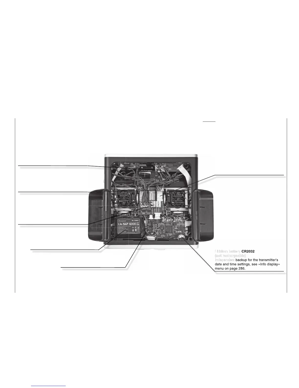
Bottom side transmitter interior
Notes:
Disconnect the transmitter battery at its
connector when performing any type of
work inside the transmitter. Never allow
solder points to come into contact with
objects as this can create short circuit
conditions.
All jacks and plugs ot described are to
be left unconnected.
Transmitter battery plug
For charging the battery and a list of suit-
able automatic chargers, see page 19
Lithium battery CR2032
(not rechargeable)
Independent backup for the transmitter's
date and time settings, see »Info display«
menu on page 286.
Transmitter battery
Observe charging rules, see page 18
Plug-in locations
Six free plug-in locations for additional
switches are standard, see page 23
These switch plug-in locations can
be used in any sequence.
Plug-in location
Three free plug-in locations for proportional
rotary control modules.
INT PPM plug-in location
One free plug-in location for connecting
an additional – internal – RF module
Plug-in locations (UVR, 5-pole)
eight free plug-in locations for future
rotary control installations.